I’ve been wanting to revisit my original Clamps pin badge for a while and replace the 5mm through-hole LEDs with reverse mounted SMD LEDs like my more recent Skeletor and Roberto PCBs.
Despite getting pretty close to sending the design off for fabrication, I was concerned that the product just wasn’t different enough from the existing Clamps design. So I decided to create my first Simple Add-On!
For those unfamiliar with SAOs, they’re little add-on boards for conference badges. The SAO standard contains provision for power, I2C comms and two GPIO pins. For this project we were only interested in the power and ground pins, which makes things slightly more straight-forward as all I needed to do was replace the existing CR2032 battery holder.
There are a number of built-in footprints for the 2×3 pin headers but they don’t take into account the shrouded connector that is suggested by the standard. So the first job was to edit one of the built in footprints to make each of the pads longer (for easier soldering) and to add a silkscreen bounding box (so that I didn’t put anything in the area the plastic shroud would occupy).
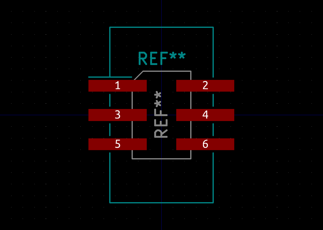
In hindsight I probably ought to have added an indication of which side the slot on the shroud should be, but hopefully any documentation I put together will make that clear.
Removing the CR2032 battery holder left a lot more free space down near the bottom of the board. This just so happens to be right behind Clamps’ mouth! I’d always wanted to squeeze some more LEDs on the original board but didn’t have the space. I toyed with the idea of having 2 LEDs behind the mouth panels, but eventually went with 3, and I’m glad I did as you’ll see later.
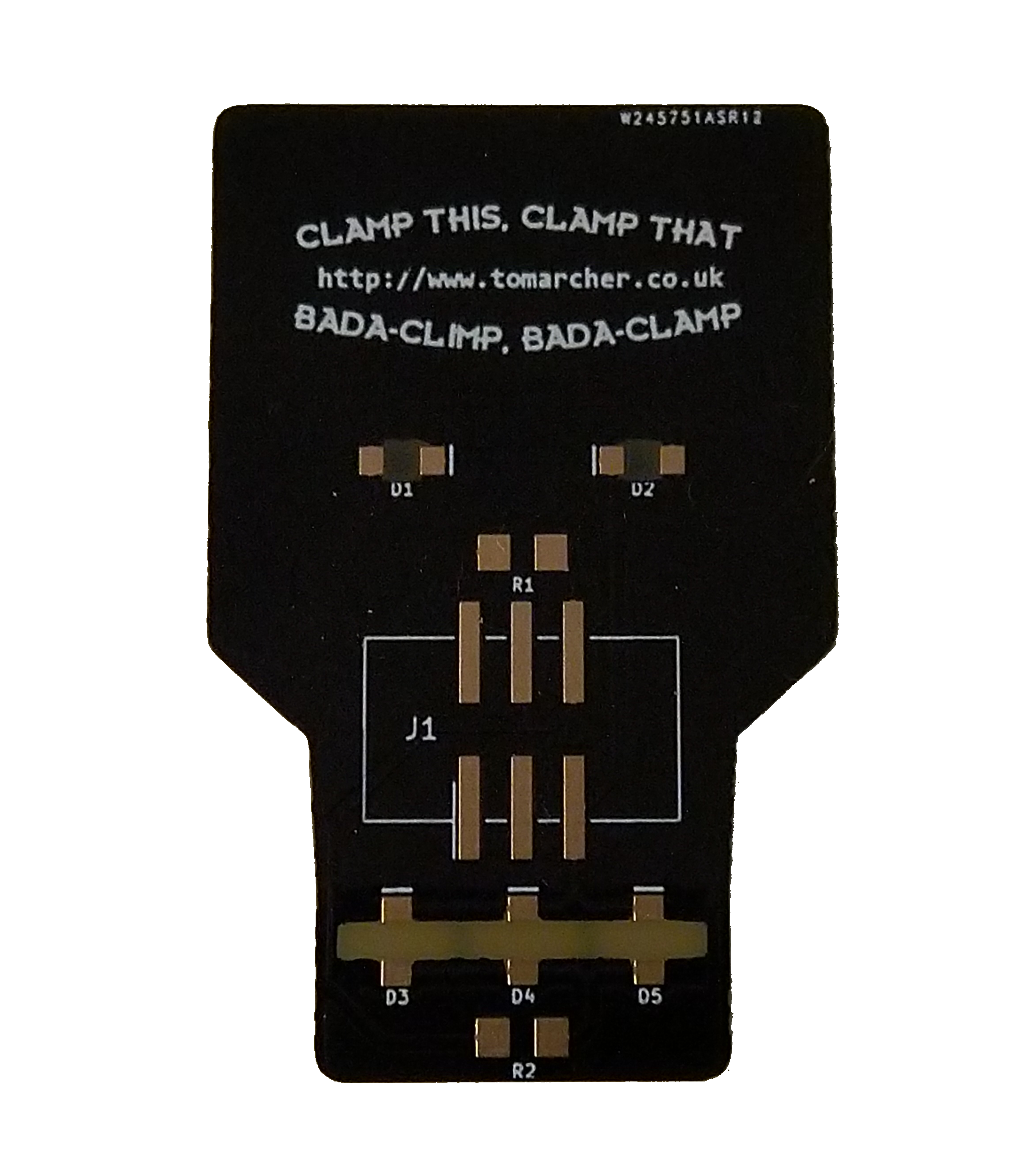
On the original Clamps badge, the eyes were white silkscreen, so I had to adjust the layers slightly so that they’d be bare FR4. While I was doing that, as an added flourish I added one of Clamps’ famous quotes using a Futurama font I found online. As ever, this was all done in Inkscape and processed using svg2shenzehn.
The last thing left was to create gaps in the soldermask for the LEDs to shine through, which for this PCB were two keep-out squares behind the pupils (like Roberto) and a keep-out rectangle behind the mouth. These are shown below in green.

Since my last run of PCBs, PCBWay have added an online gerber viewer (above) to their site. It’s really nice to be able to inspect the files that you’ve uploaded and make sure everything is correct. The PCBs were delivered a week after I ordered them and that included the engineers double checking a couple of things before they sent the board off for fabrication. It’s nice to know they’re looking out for any silly mistakes I’ve made.
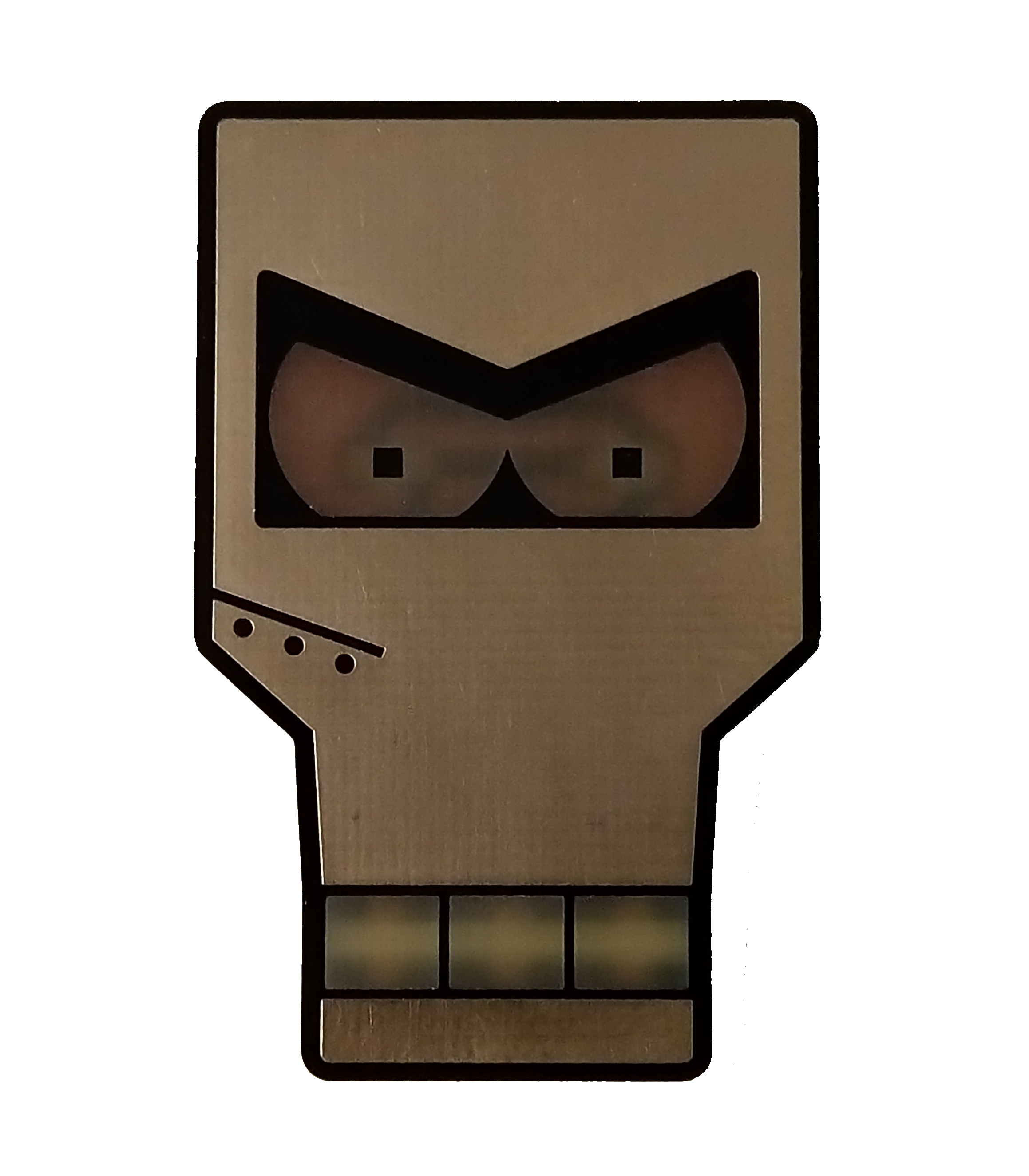
The ENIG gold finish is fantastic, certainly comparable with DirtyPCBs who set the standard with the old Clamps badges. The FR4 is a little more transparent than their previous PCBs, but seeing as I’m going to be shining LEDs through it from the back, I can’t really complain. The silkscreen quote came out really crisp too!
With the boards in hand, the next job was selecting some resistors. Ideally I’d like to have the mouth shine slightly less brightly than the eyes, so I went with a 330ohm resistor for R2 and a 100ohm resistor for R1. Handily these are values I use in some of my other products so I usually have plenty in stock.
I’ve got pretty good at soldering the SMD LEDs on upside down, but that doesn’t mean I don’t occasionally solder them back-to-front. The last thing to solder on was the header pins. I haven’t yet received my shrouded headers, so I had to make do with some I had left over from the Fireplace project. Still, they do the job and the extra large pads really helped with soldering.
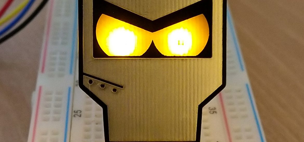
Here’s the final product running off 3V3 from a Raspberry Pi:
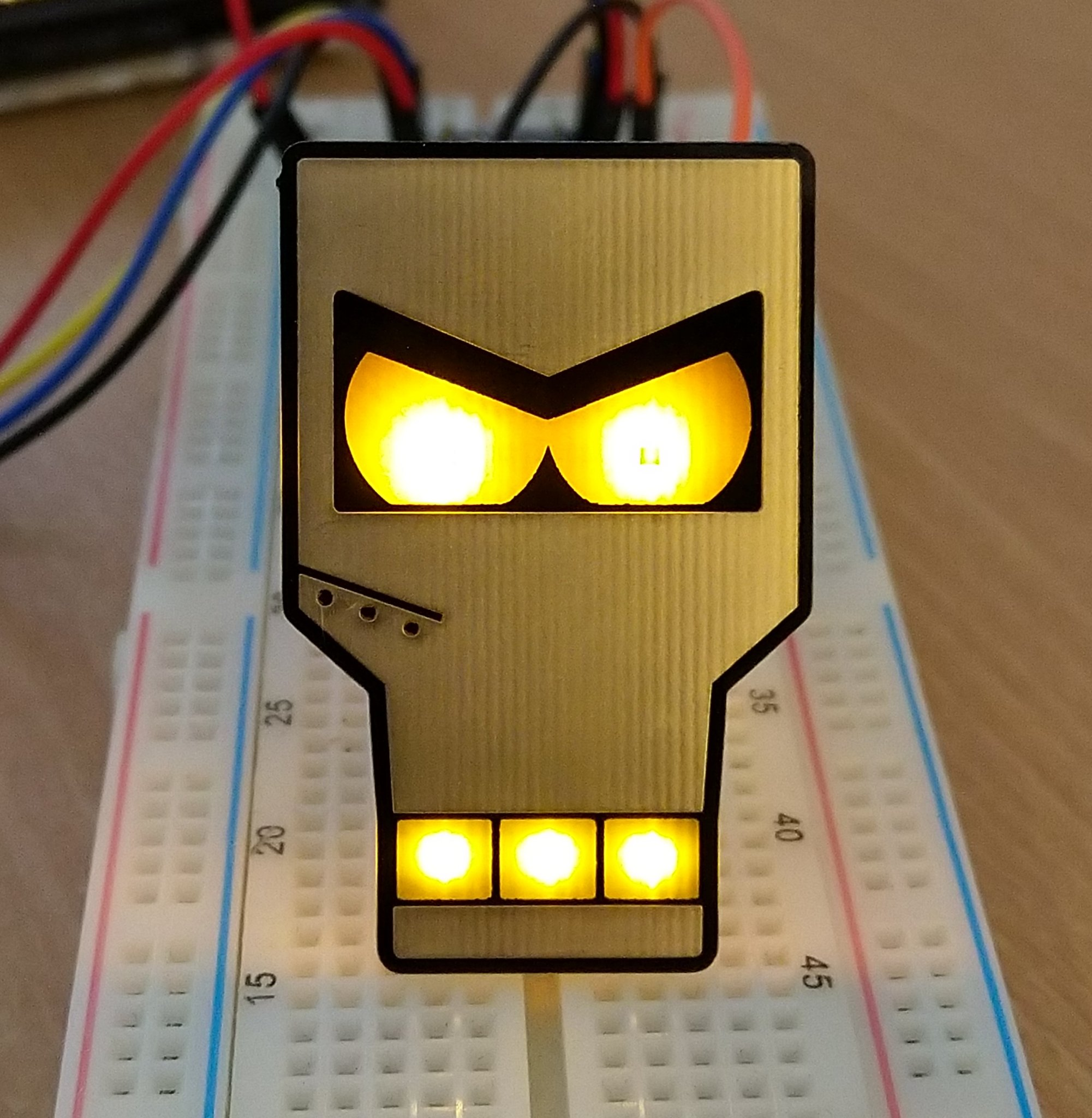
The effect behind the mouth looks fantastic! I’m hoping to re-open my Tindie store pretty soon so I’ll get them listed as soon as I can.