It’s been a couple of years since I last posted about my Battlestar Galactica Chronometer. In this post I’ll wrap up all of the progress since then and hopefully bring the project to an end.
We last left this project in 2020 having populated the “seconds” (yellow) and “minutes” (red) rings on a fresh PCB. At the beginning of 2021 I got around to populating the inner “hours” (orange) ring which are controlled using a second HT16K33 LED driver board. That’s probably overkill for just 12 LEDs but it means I can control all of the LEDs using I2C.
With the LEDs added, next up was coding some new animations to make use of them:
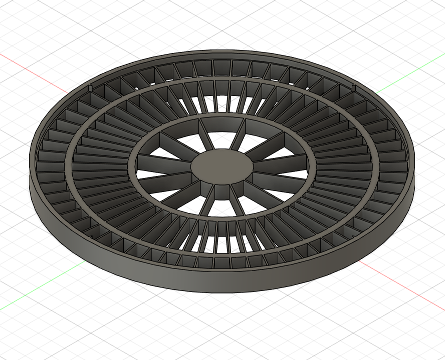
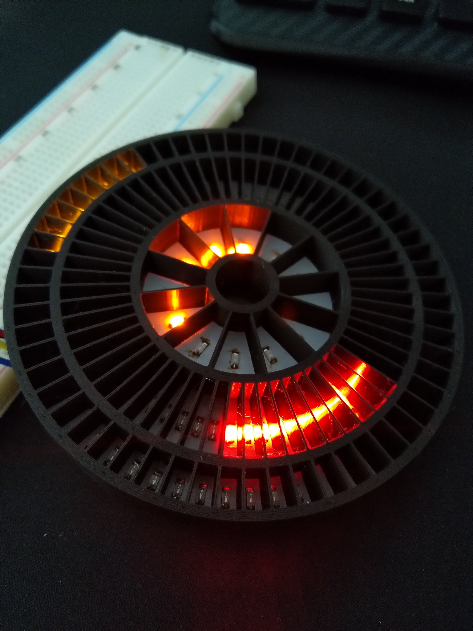
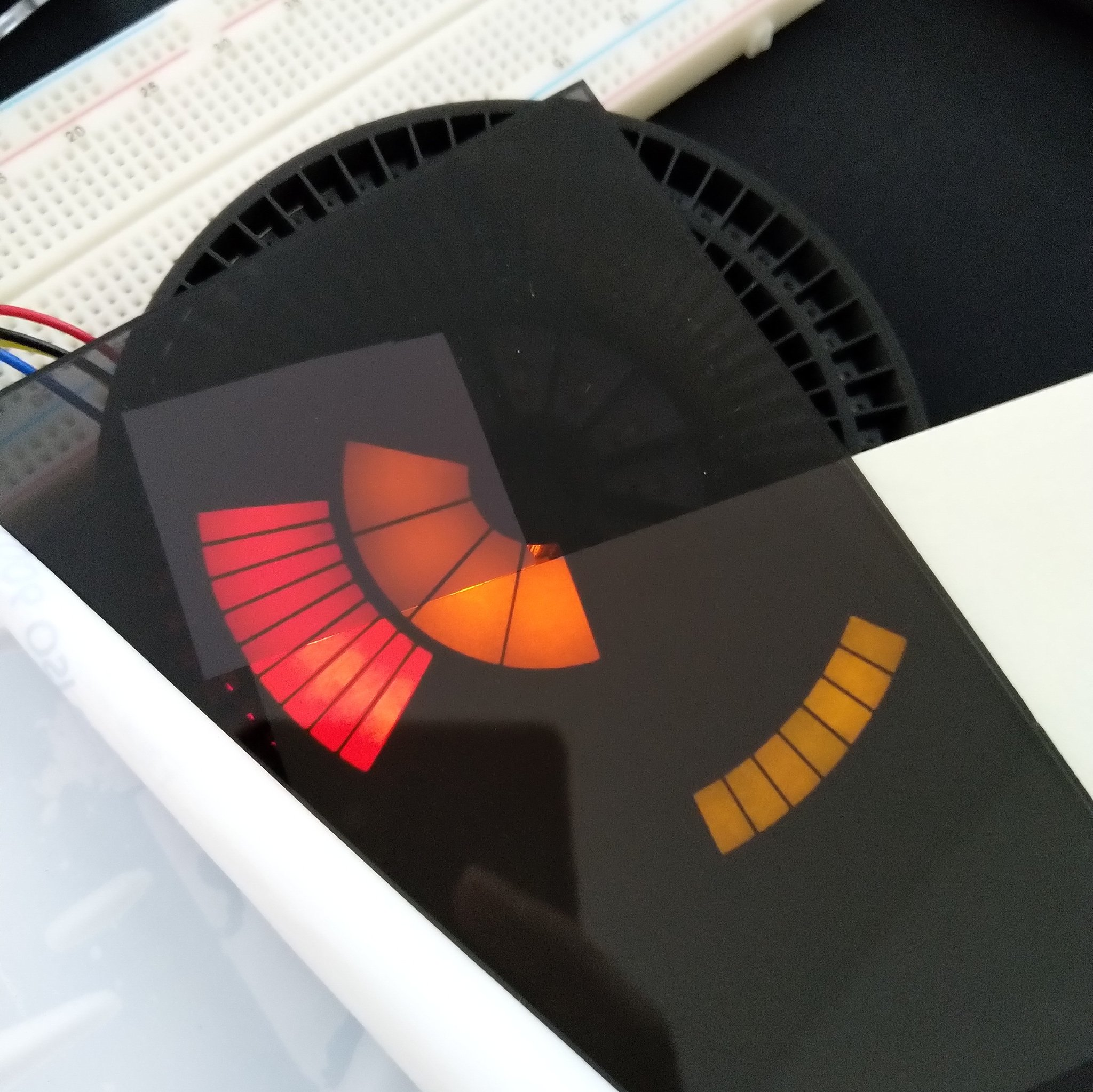
Having sorted the LEDs and wiring my attention turned to the light guide. The aim here to is for each LED to illuminate a distinct segment with little or no bleed. At the time I didn’t have access to a 3D printer so I got this printed via Treatstock and it came out great. In the third image below you can see my experiments with different diffusion materials, namely acrylic, white adhesive vinyl and paper.
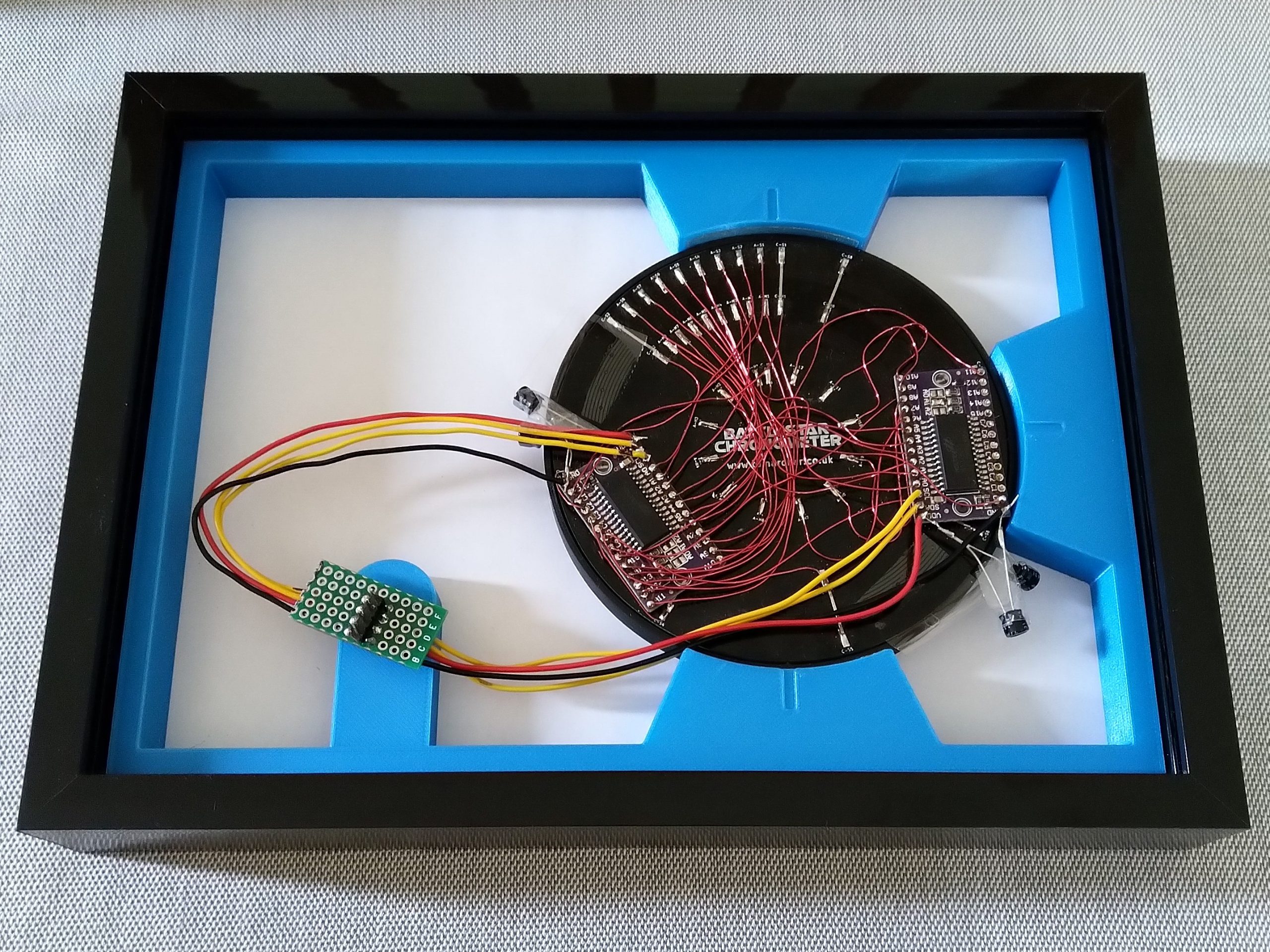
Another hiatus brings us to September 2022. I finally found a box frame that would serve as an enclosure. I swapped the provided glass with black tinted acrylic and the provided spacer with a 3D-printed replacement which also holds the light guide. A sheet of paper sits between the light guide and the acrylic to provide some additional diffusion.
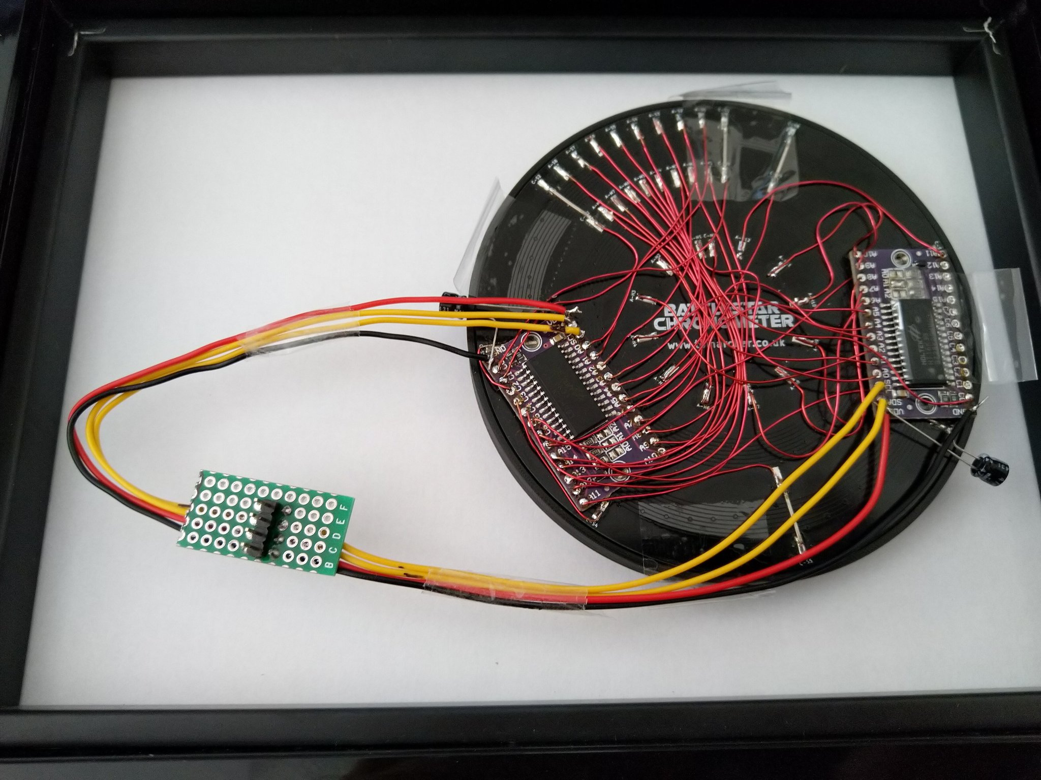
Around this time I noticed that the red LEDs were exhibiting a weird “rolling shutter” effect. This was somewhat reduced by the addition of the pictured capacitors but was particularly visible when all the LEDs were illuminated. At this point the LEDs were being powered from the Raspberry Pi 5V rail which was perhaps asking a bit much. Powering the second HT16K33 from an Arduino I had to hand seemed to confirm that it was a power supply issue. To remedy this I purchased a small Mean Well power supply. This is rated up to 7A at 5V which should be ample for this project and any future LED projects.
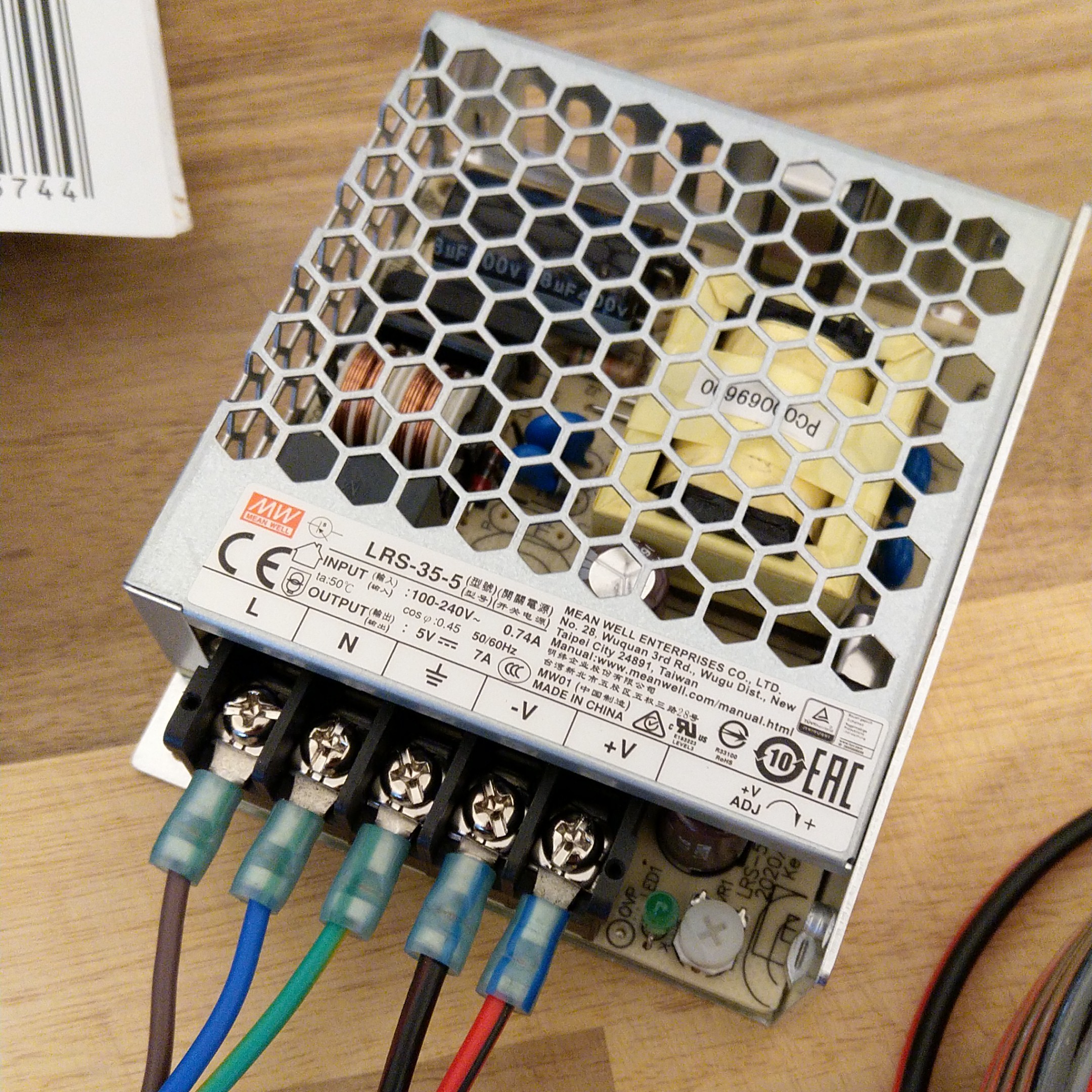
I also opted to power the Raspberry Pi from the same power supply rather than using the official PSU. I was a little nervous about this but I’ve had no problems so far.
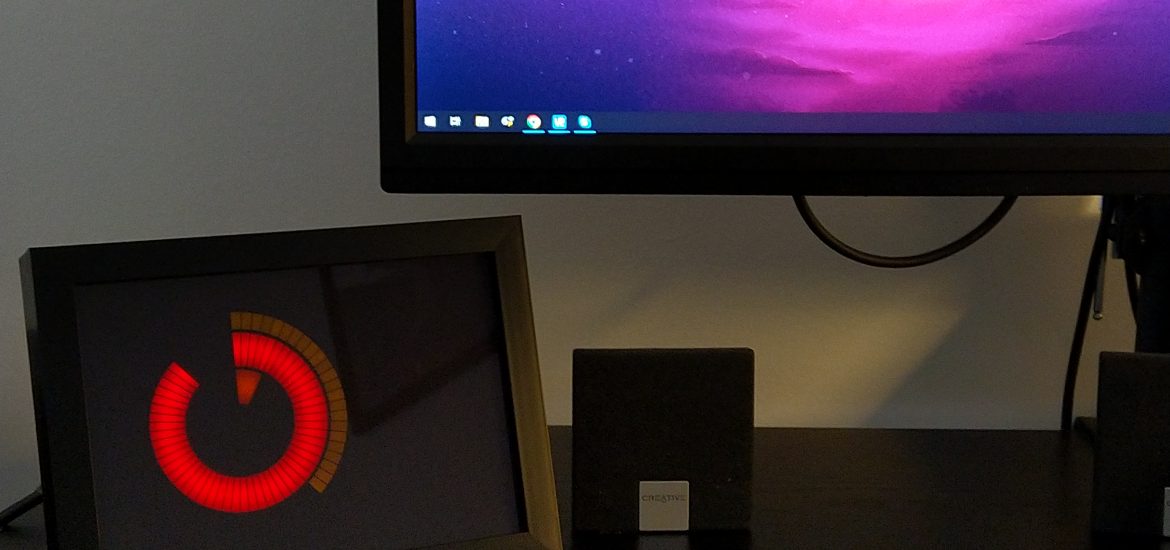
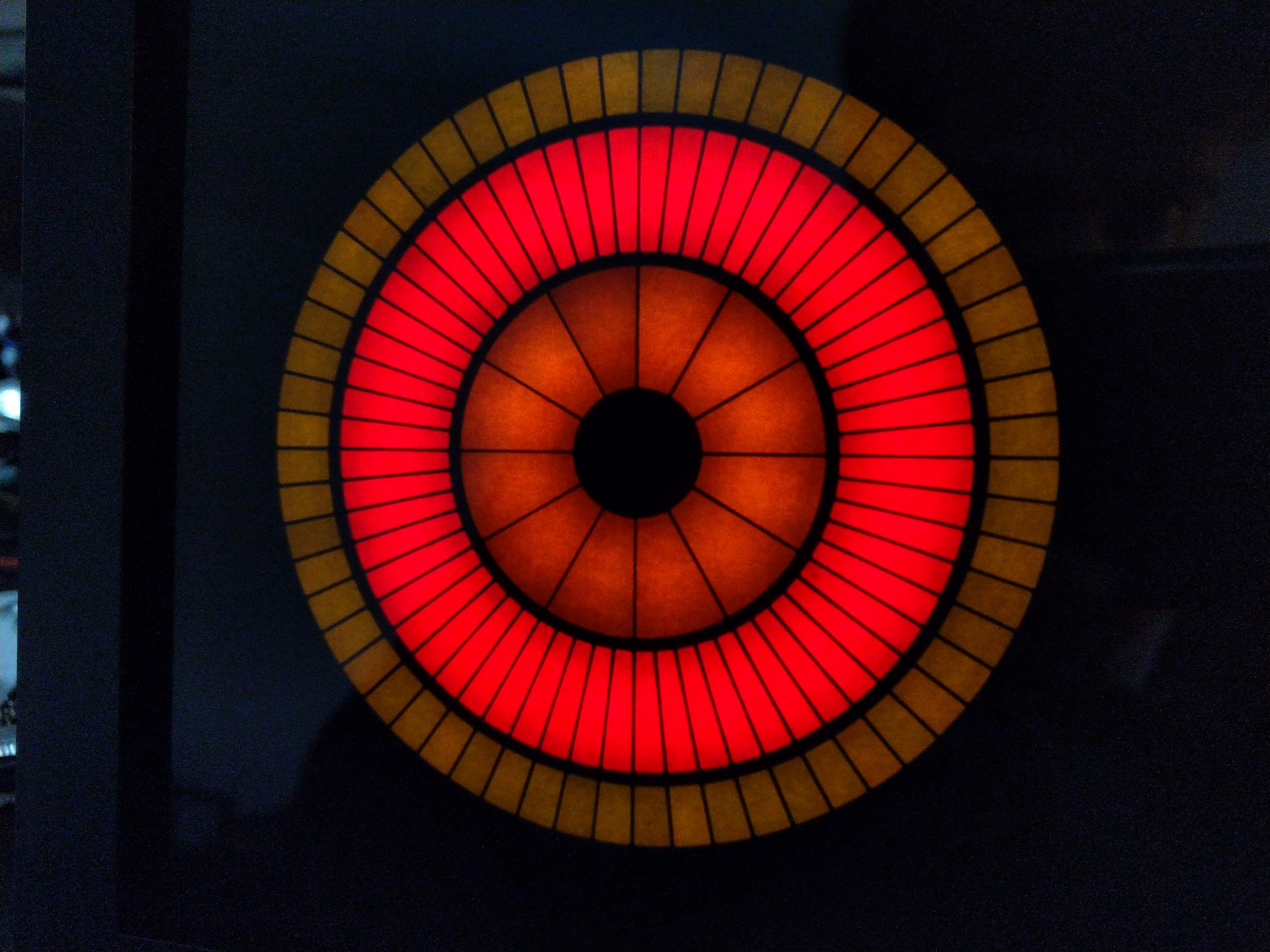
Here are some photos of it fully assembled:
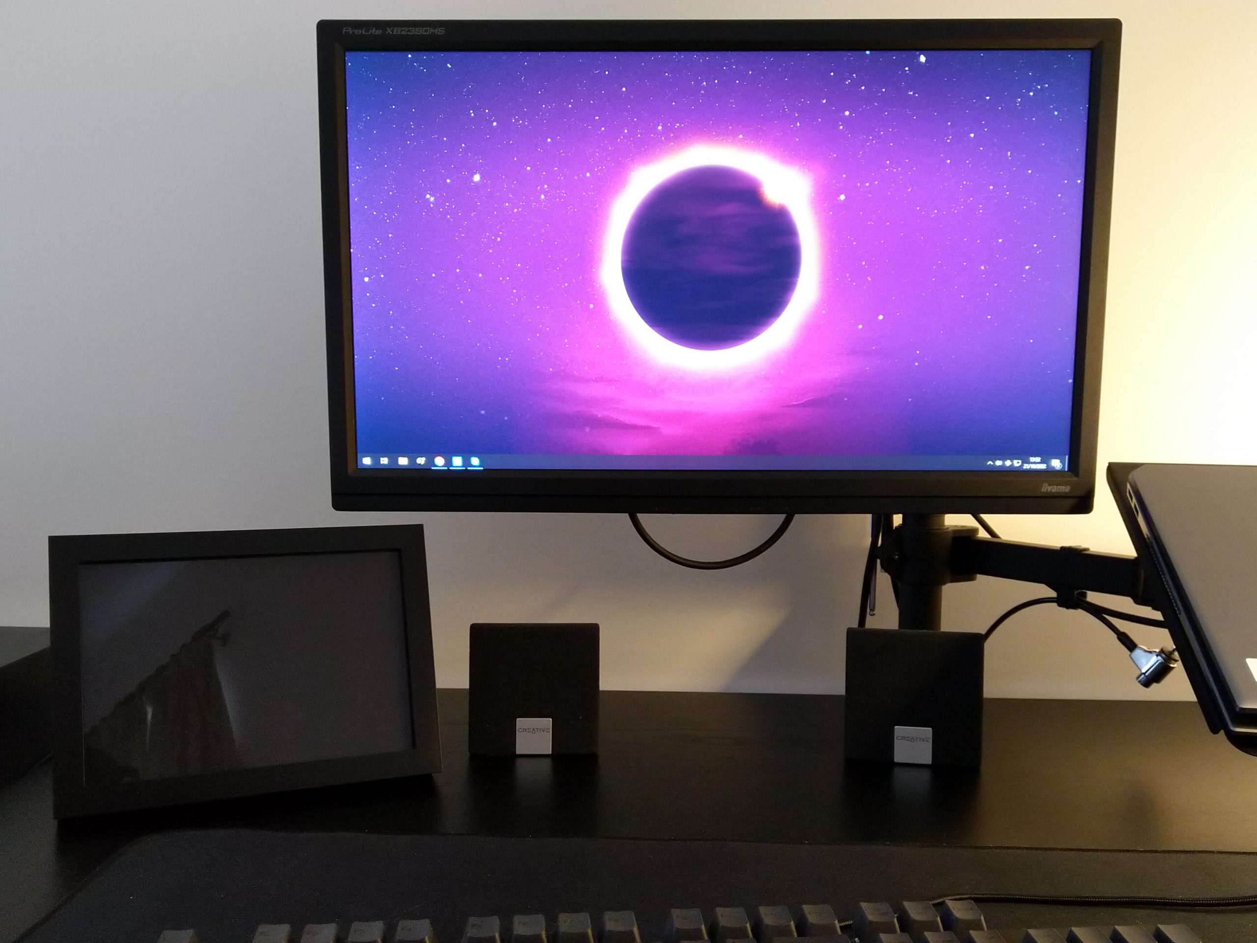
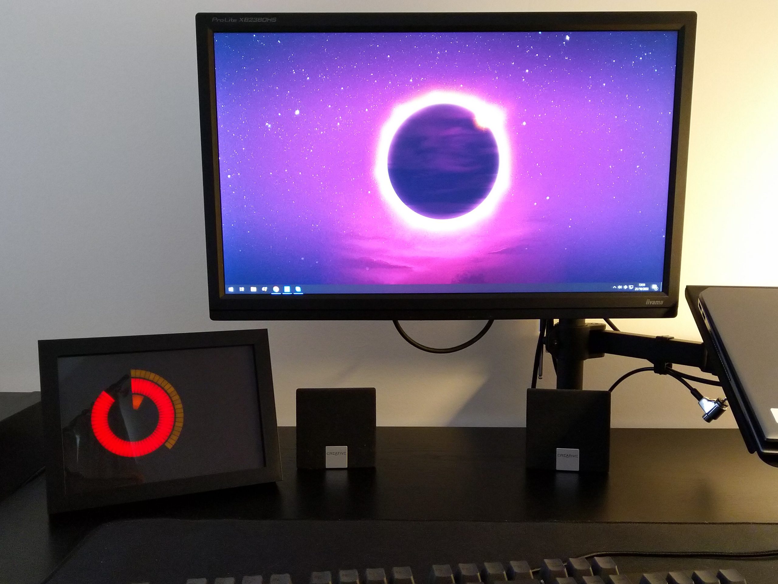
Up close you can definitely see some of the texture from the paper diffuser layer. I might end up replacing it with some adhesive vinyl.
When I originally designed the PCB I didn’t have an enclosure in mind. This made the wiring much more difficult than it really needed to be and was likely partially responsible for some of the flicker I was seeing earlier. If I revisit this project, I’d definitely take advantage of a larger PCB to host the LED drivers and replace the enamel wiring.
My only other slight criticism is that the red LEDs overpower both the orange and yellow LEDs. With the “hours” segments being so large they would definitely benefit from a second or third LED per segment and the second LED driver board could easily accommodate them. With the “seconds” and “minutes” LEDs being wired to the same driver I can’t reduce the brightness of the red LEDs alone. I might investigate some alternative drivers that allow per LED brightness control.