This post provides instructions for using the Battlestar Chronometer PCB.
Matrix Layout
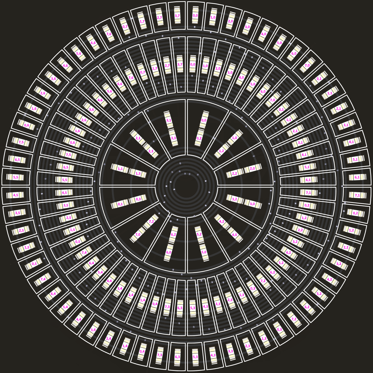
The “seconds”, “minutes” and “hours” rings are matrices where index [x,y] corresponds to [column, row] or [anode, cathode].
I2C Addresses
The matrix I2C addresses are listed below.
Note: The matrix I2C addresses cannot be changed.
| Matrix | Address |
|---|---|
| Seconds | 0x70 |
| Minutes | 0x71 |
| Hours | 0x72 |
Arduino (5V) Operation
The Chronometer has the I2C pull-up resistors connected by default.

Connect the screw terminals to 5V power and ground. Connect the adjacent SDA and SCL pins to Arduino.
Arduino / C Matrix library: https://github.com/adafruit/Adafruit_LED_Backpack/tree/master
Sample Arduino C code: https://gist.github.com/Tom-Archer/f22e123e8c22ae0b721cc36e6d0b5d5d
Raspberry Pi (3V3) Operation
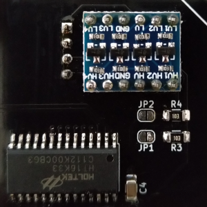
Install the bidirectional logic level converter and the adjacent header pins.
The I2C pull-up resistors are not required, the jumpers ought to be de-soldered. If wishing to use Arduino/5V after the bidirectional LLC has been installed, there is no need to bridge the jumpers
Connect the screw terminals to 5V power and ground. Connect the 3V3, GND, SDA and SCL pins to Raspberry Pi.
Raspberry Pi / CircuitPython Matrix library: https://github.com/adafruit/Adafruit_CircuitPython_HT16K33/tree/main
Sample Python code: https://gist.github.com/Tom-Archer/6bfd9f017b28e601e4d484e4b21ceb14
3D Print File
6″x8″ frame: https://www.printables.com/model/420270-battlestar-chronometer-frame
The frame contains holes for M3 bolts.