The Easter Bank Holiday weekend was the perfect opportunity to get through a lot of soldering.
I started off by soldering all the components to get the orange “hours” LEDs running. This was the smallest amount of soldering needed to prove the concept – fortunately it all worked.
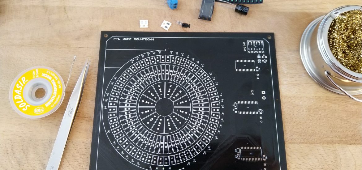
I’m glad I added the test pads, they provided two uses. The first, checking that the LEDs were oriented and seated correctly; the second, ensuring that the legs of the HT16K33 chips were making good connections. I did have to refer to the board layout a few times as the labels on the test pads are a little small.
Soldering the HT16K33 chips was a little tricky but not impossible. The fine tip of my soldering iron helped, even if it did get a little warm, I alternated pins to avoid overheating the chip. As I mentioned previously, it would have helped had the pads on these footprints been larger. This is something I’ve fixed for any future re-spins of this board.
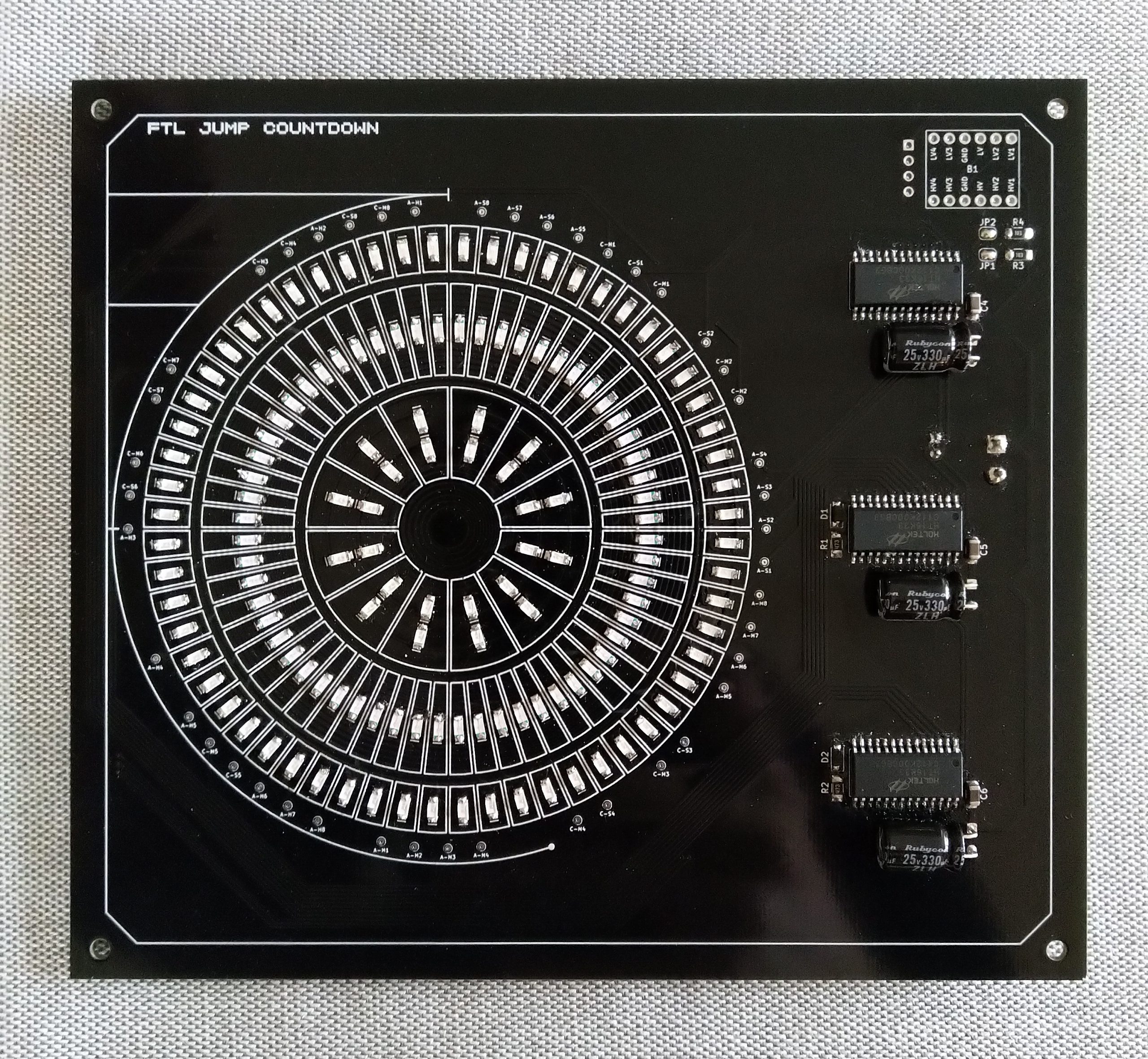
After another soldering session I’d added the remaining 120 LEDs and supporting components.
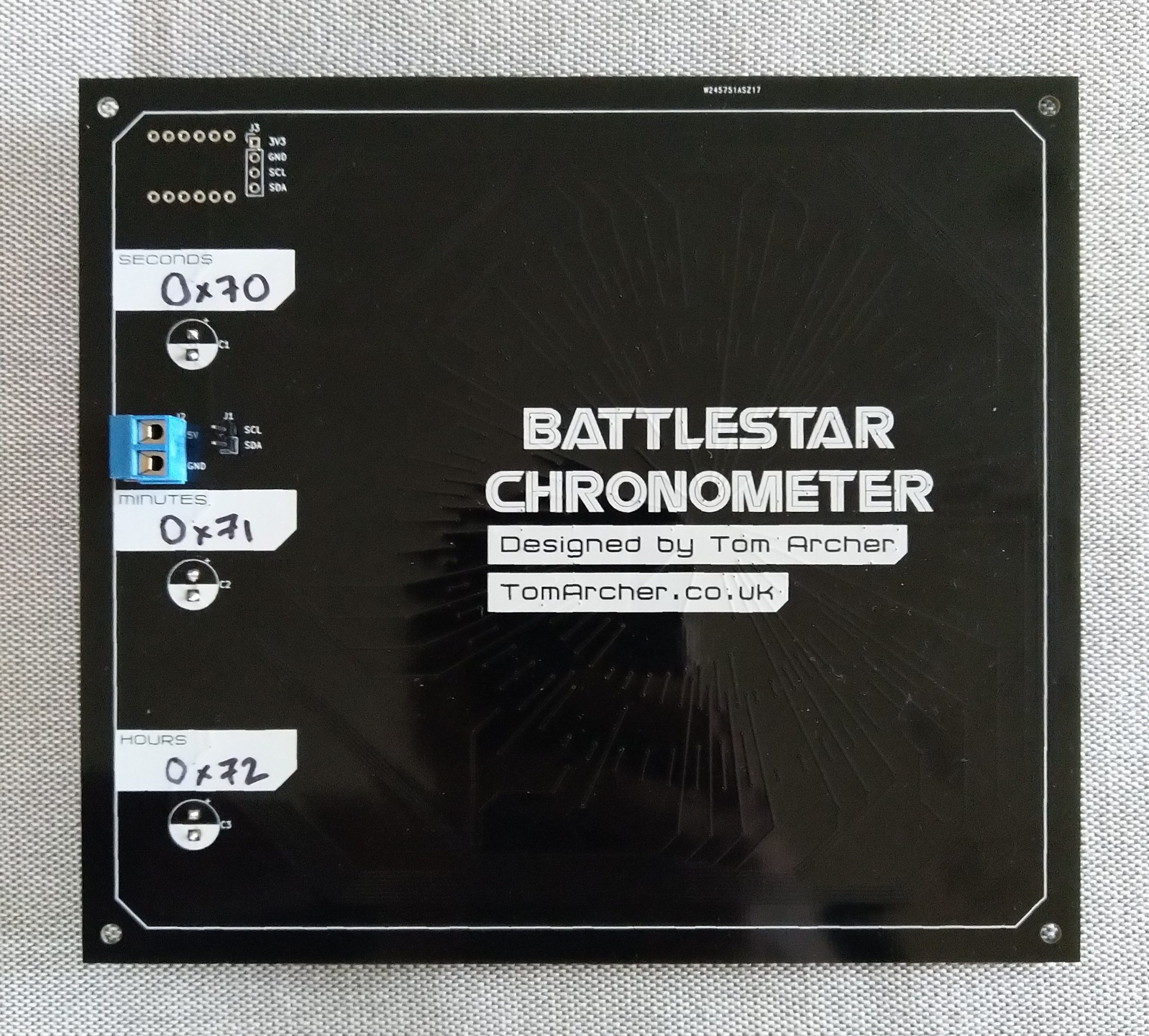
The matrix labels on the back provide a handy place to write the I2C addresses. The addresses aren’t configurable but I wasn’t confident enough to make them part of the silk-screen.
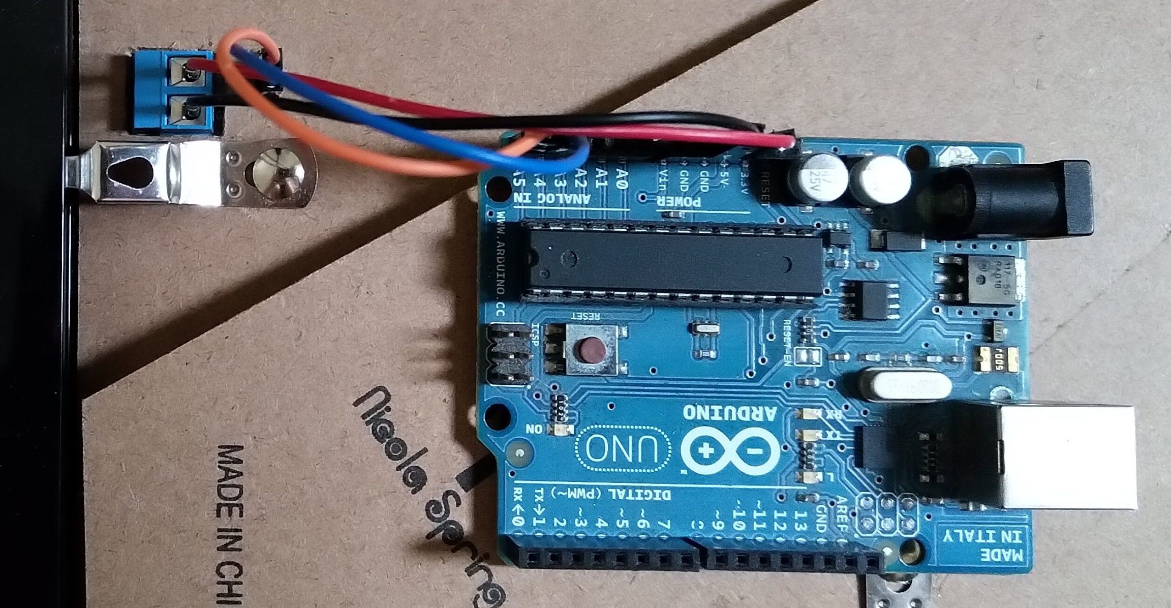
For testing, I’ve been using an Arduino UNO as the wiring is a little simpler. With the Arduino I’ve not noticed any of the power issues that were present in the previous version. This isn’t entirely surprising given the rats nest of wires that this version has done away with.
Since I had to port my Python code across to Arduino C, I took the opportunity to add some additional animations.
I was then ready for final assembly. The PCB, 3D-printed spacer and backboard are all joined together with some M3 bolts. I made some cut-outs in the backboard to accommodate power and comms. I did get a little bit lucky with the position of the screw terminal. As you can see in the photo below, the wiring is much more manageable:
I’d added the screw terminal to allow for heavier gauge wire for power supply. In future versions I might also add 5V and GND header pins alongside the screw terminal for convenience. It might also be handy to add some additional “output” headers to the PCB for daisy-chaining other fun stuff.
With the 5V comms proven, the next step was to check the 3V3 comms. The bi-directional logic level converters I’d bought dropped in nicely. Since they have their own pull-up resistors on the 5V side, I had to unsolder the jumpers on the PCB.
Powering the display directly from the Raspberry Pi 5V pin did show some slight “ghosting” that we had with the previous version. However, swapping over to the Mean Well PSU got rid of it completely. I suspect the 5V rail on the Raspberry Pi isn’t quite up to the task of powering all the LEDs.
In the next post I’ll show off some of the animations and work on getting the remaining four PCBs assembled for sale on Tindie.