The PCBs have arrived and a few things have changed since the last post so here’s a quick update.
As I started to order components I had a bit of a change of heart. The original plan was to use some off-the-shelf HT16K33 breakout boards to save myself some trace routing and some soldering. The more I thought about that, the less I liked the idea, so I ended up replacing the breakout boards with discrete matrix drivers, capacitors, diodes and resistors.
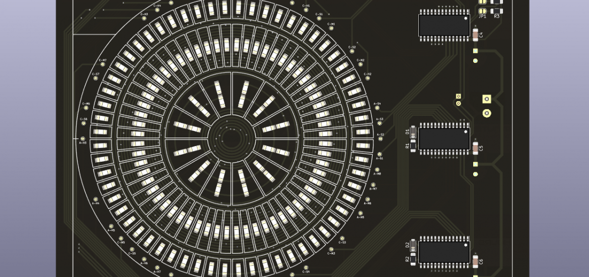
Each of the HT16K33 chips has a decoupling capacitor and two of them each have an additional diode and resistor to set the I2C address. This was a lot of extra routing, some of which is now taken care of by the Python script but a lot of it was done manually. While I was tweaking the Python script I also increased the track widths inside the “matrix” so that they’re consistent with other track widths on the board.
A nice side effect is that there’s now a lot more space between the matrix drivers. This has allowed for better positioning of the screw terminal and headers while also allowing me to squeeze in positions for some optional through-hole electrolytic capacitors should I need them. The final change was to add some pull-up resistors for the I2C lines. These can by optionally connected using the adjacent solder links. This should mean that the PCB is somewhat microcontroller agnostic.
The BOM works out a little cheaper by doing this and I think the PCB is going to look a lot neater, even if it does make the soldering a bit trickier.
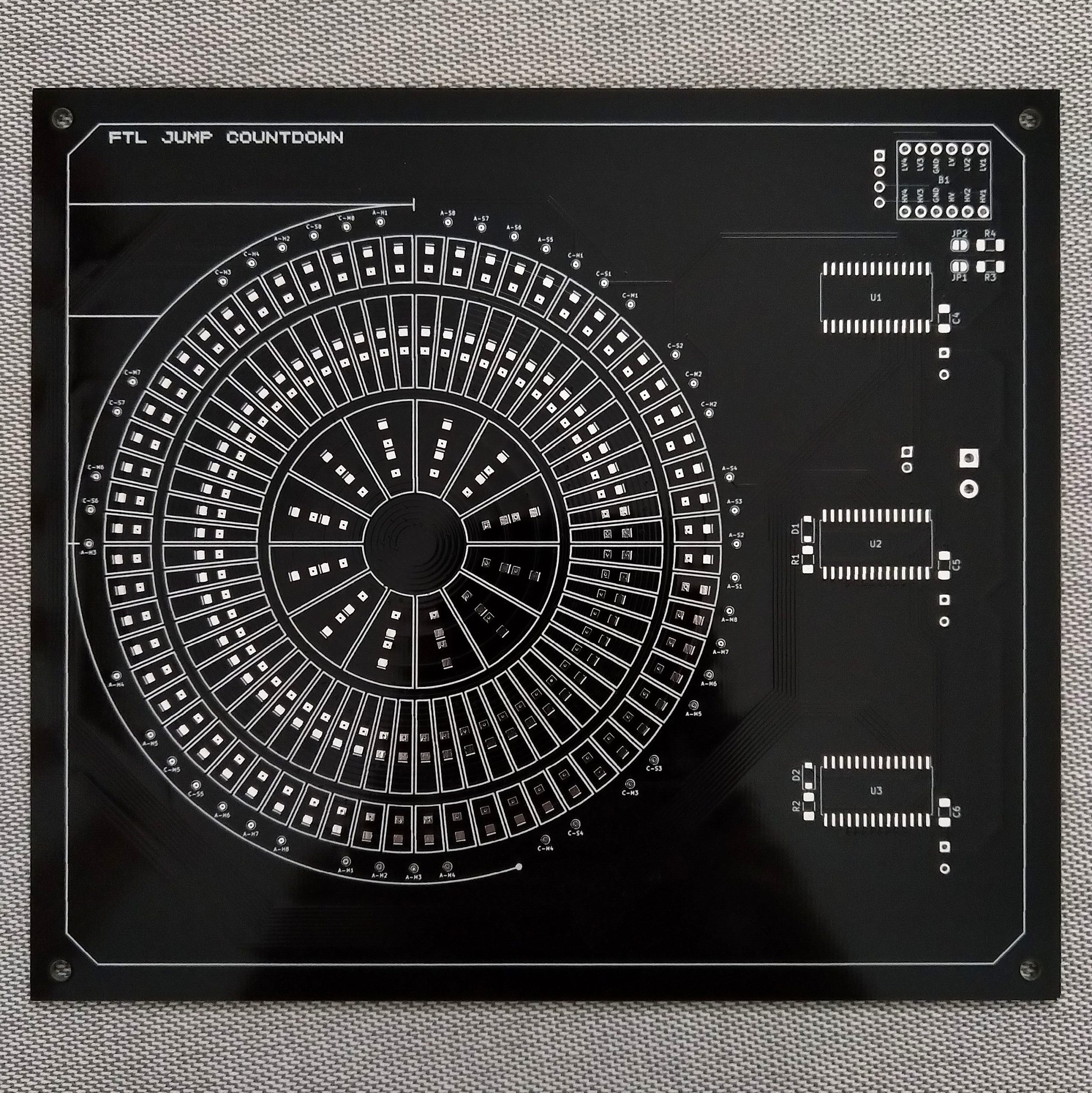
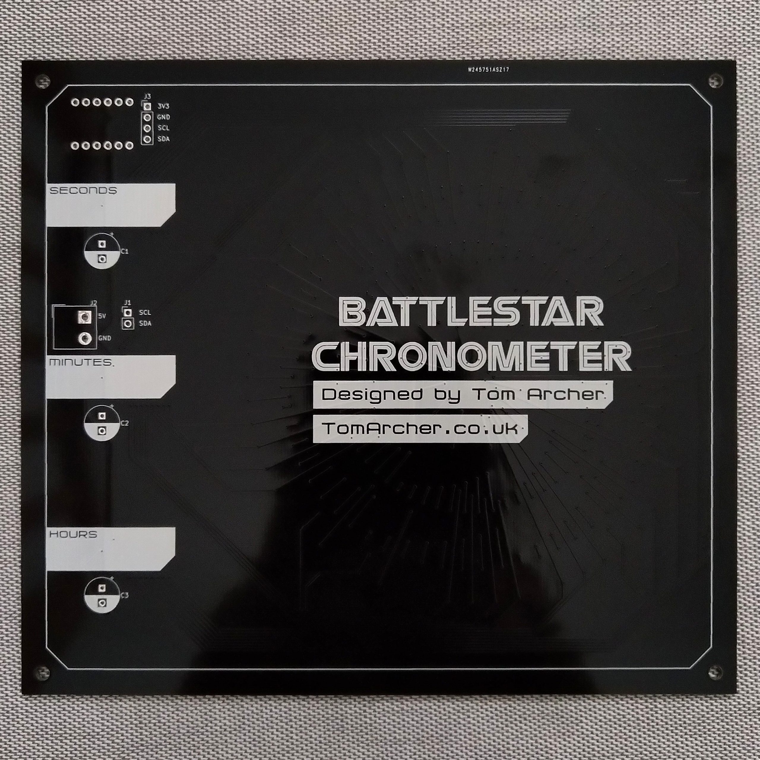
With all that done it was time to send the files to PCBWay for fabrication. As I was putting together the order I noticed black solder mask came at no extra cost so I opted for that instead of the standard green. Despite placing the order on a Sunday, the PCBs had been shipped within two days. They look fantastic as always. If I had one very minor criticism, it would be that the printing of the small circles around each of the test pads is a bit spotty. That’s probably on me though, now I see the board in the flesh it occurs to me that they are very thin lines. Should I get more of these PCBs manufactured I’d probably just remove those details. Otherwise, everything else looks great.
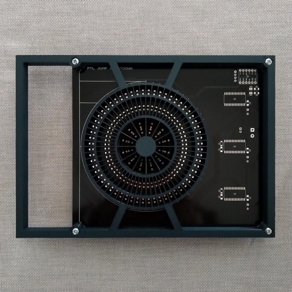
I’m somewhat surprised by a PCB fitting perfectly in the frame I 3D-printed. I was half expecting to have to do a few iterations to get that right.
Now all I’ve got to do is lots of soldering. That will have to wait until next time.