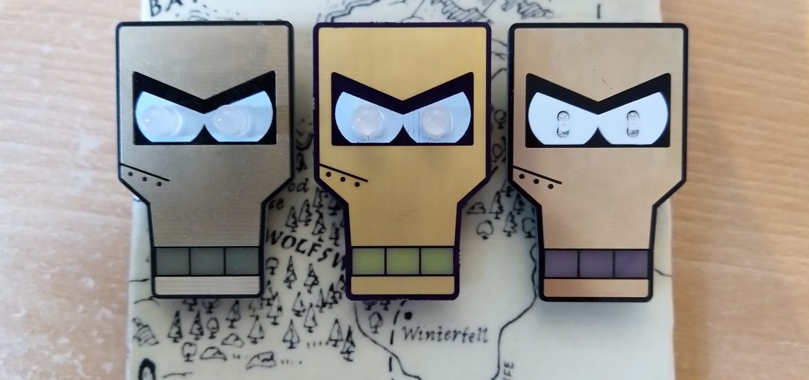
Just in time for the weekend all the parts for version 2 of my Clamps badge arrived!
Here’s a look at the bare PCB from OSHPark – annoyingly I had issues with the front ENIG finish on two of the badges, and the front soldermask on all three to varying degrees. OSHPark have sent some replacements off for fabrication but I decided to press ahead with the best of the bunch.
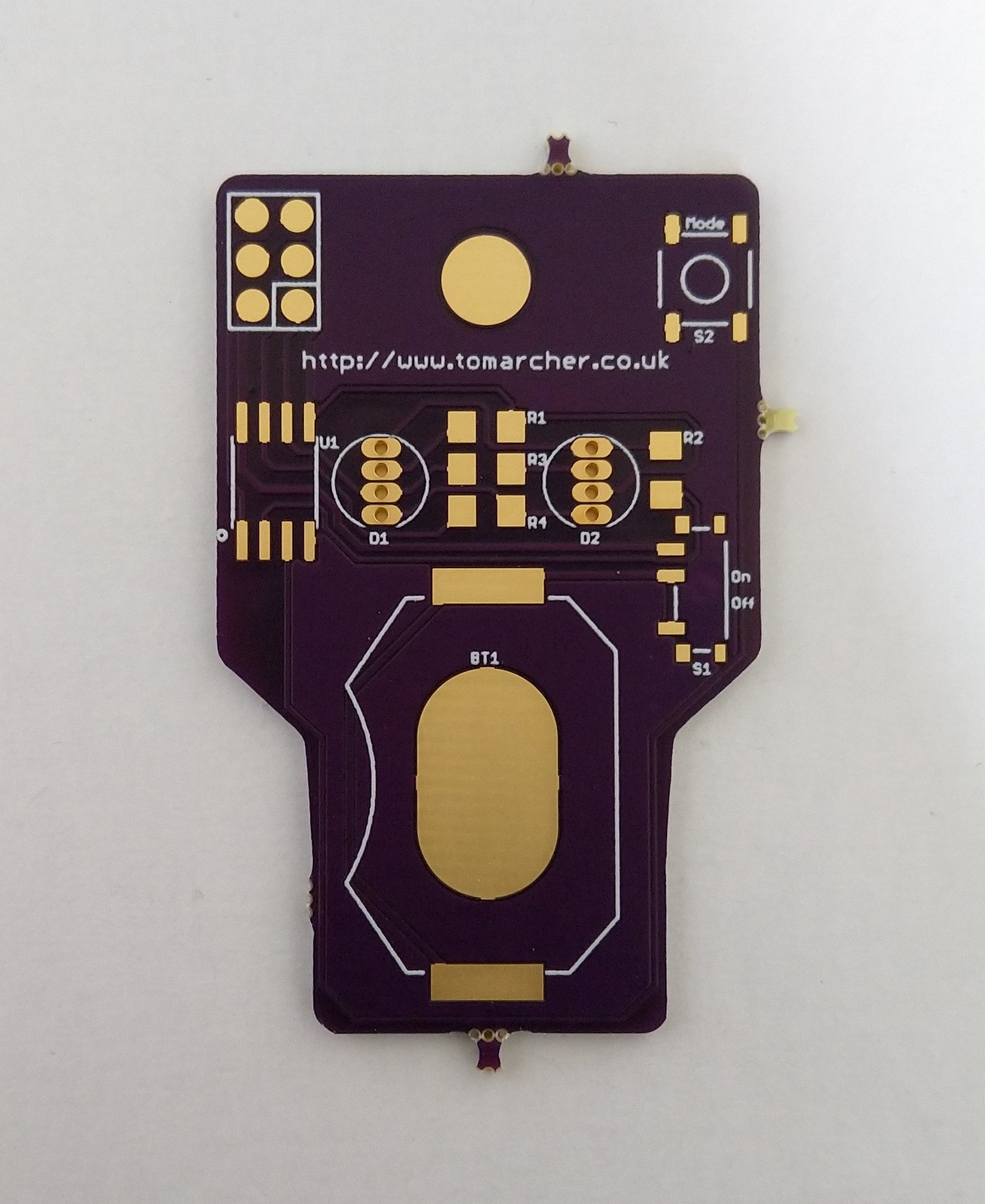
The purple soldermask is, as ever, lovely and it’s so dark on the front of the board, it’s hard to tell it isn’t black.
| Order submitted | June 8th |
| Added to panel and sent to fab house | June 8th |
| Received from fab house and dispatched to me | June 14th |
| Received by me | June 22nd |
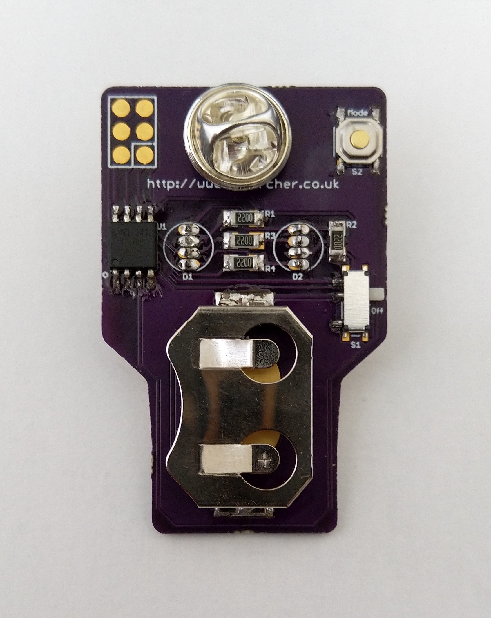
Soldering the components on the back of the board turned out to be fairly straightforward, the hardest components ended up being the RGB LEDs with the pads being so close together. It’s not the tidiest but it all works! Since I had the iron out I took the opportunity to solder some SMD LEDs (left over from the Chronometer build) onto a version 1 PCB, as seen in the header image.
While I was waiting for the PCBs to arrive, I ordered a breadboard version of the ATtiny chip so that I could get on with writing the code.
Here’s a picture of my badge setup, you’ll notice that I had to make do with some DIY RGB LEDs for testing.
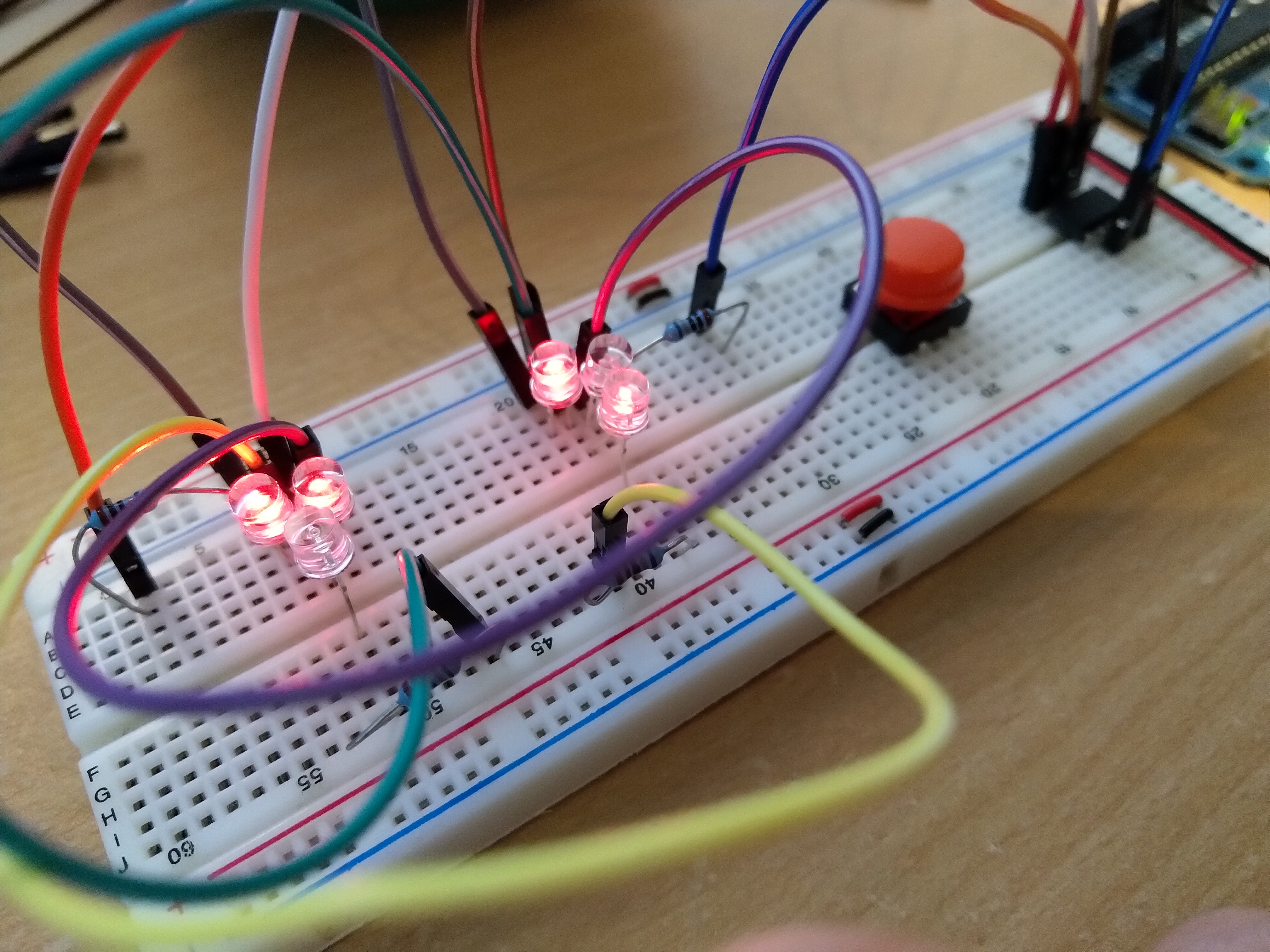
As mentioned in the previous post, this page was a great help, not only in understanding the wiring but it also provided a great starting point for the code. I’ve built on that and implemented a number of animations that can be selected using the ‘mode’ button on the back of the badge. You can find the code for the badge here.
You might notice the un-populated header on the back of the badge. This allows me to program the ATtiny85 once it’s soldered onto the badge. To do this I re-purposed my Arduino Uno and turned it into a programmer. This article proved immensely useful.
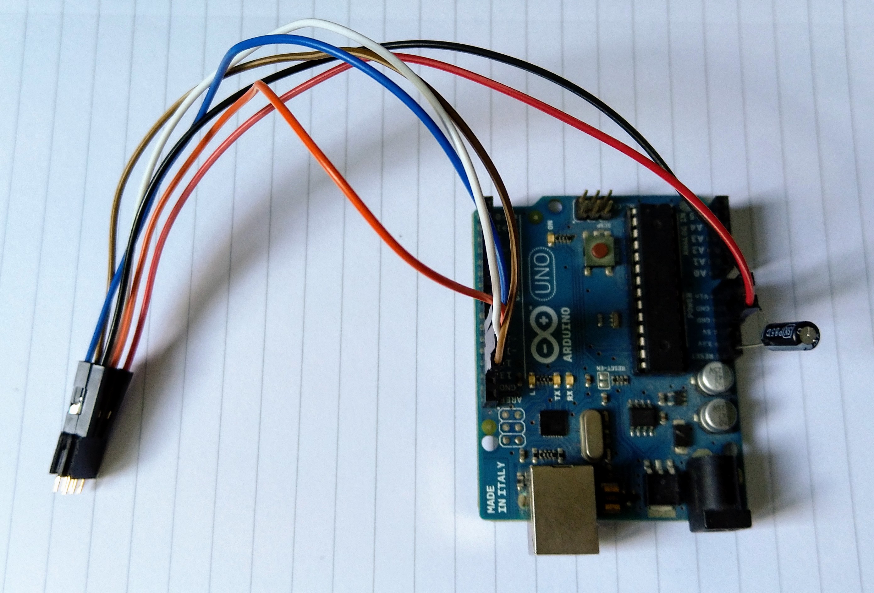
Aside from a couple of issues with flaky connections, burning the code onto the badge worked like a charm. I could definitely improve on this setup, but currently it’s something I won’t need to do too frequently. Here’s a brief video of the ‘police flasher’ animation.
All in all, I’m pretty happy with how this turned out. I may tweak a resistor value or two as currently the blue LEDs are pretty dim when the battery starts to run down. Maybe once all the version 1 badges sell out, I’ll have to get a batch of these made for Tindie.