In part 1 we designed the PCB and sent it off for fabrication. With the boards and 300 LEDs in hand, it’s time to get soldering!
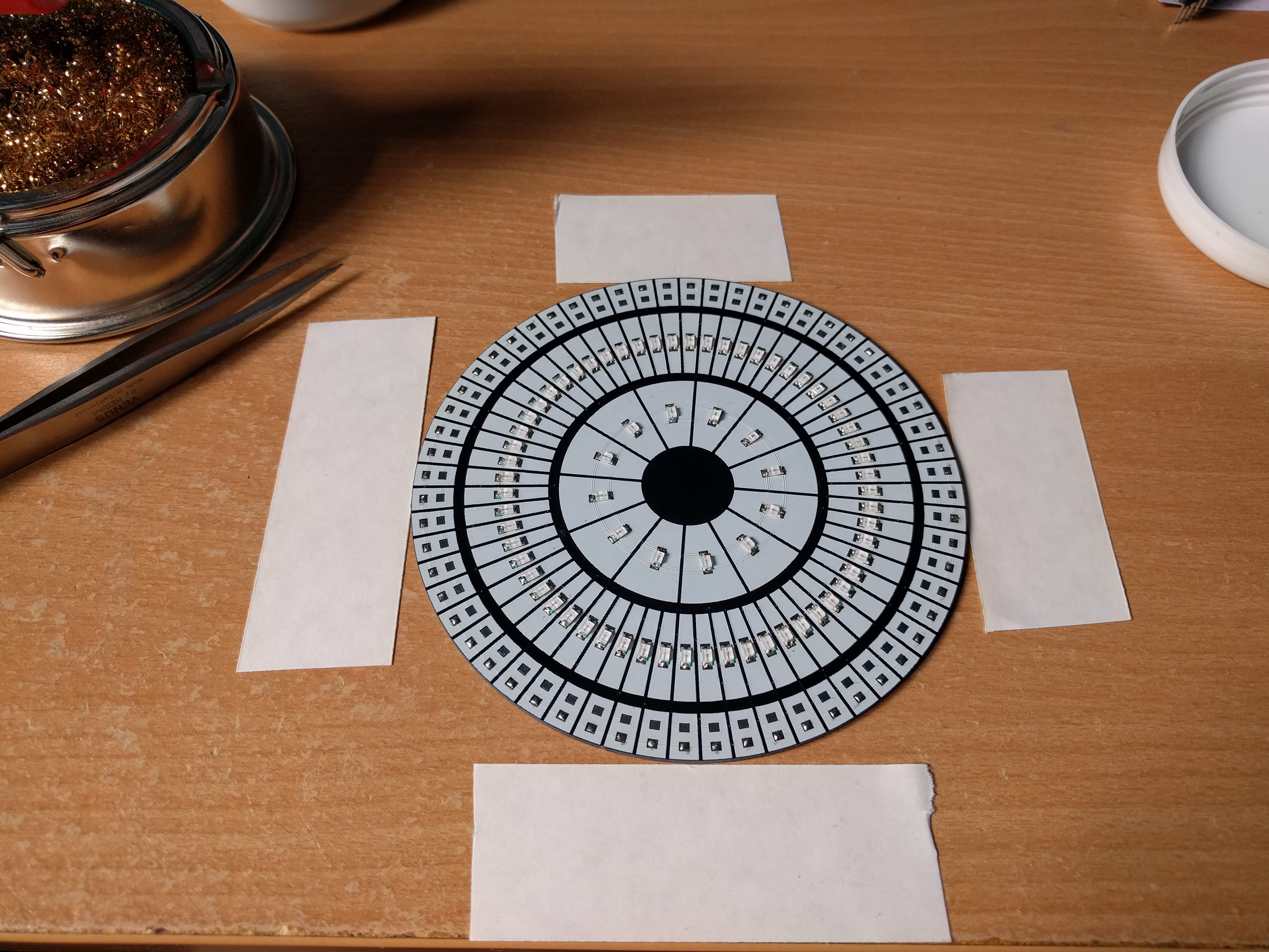
Going into this I was slightly daunted by the size of the 1206 surface mount LEDs. I started by applying solder to each of the pads on the PCB, then beginning with the ‘hours’ LEDs I tacked down one end of each LED. This allowed me to slightly tweak the position of the LEDs before then soldering the opposite end. Using some tape, I created a jig to hold the PCB while my hands were busy with the soldering iron and tweezers.
Once I’d finished soldering I gave the board a once over with some isopropyl alcohol to remove any flux/residue. Here’s the finished board: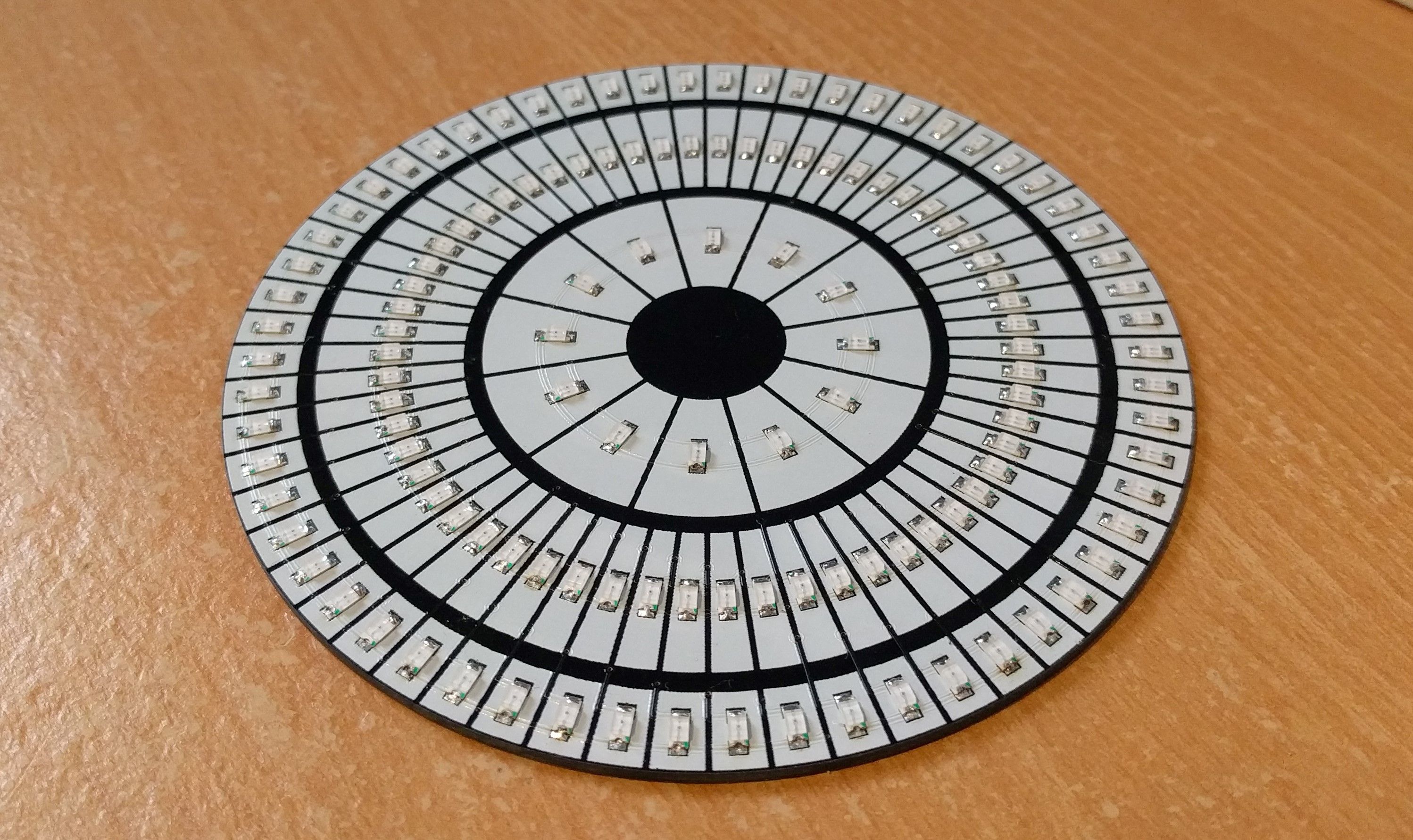
The next step was wiring! Rather than spend hours cutting wire to length I purchased some ‘jumper-jerky’ and proceeded to pull the black connectors off one end. These were then soldered to the pads on the reverse of the board. The opposite ends would then be easily plugged into a breadboard.
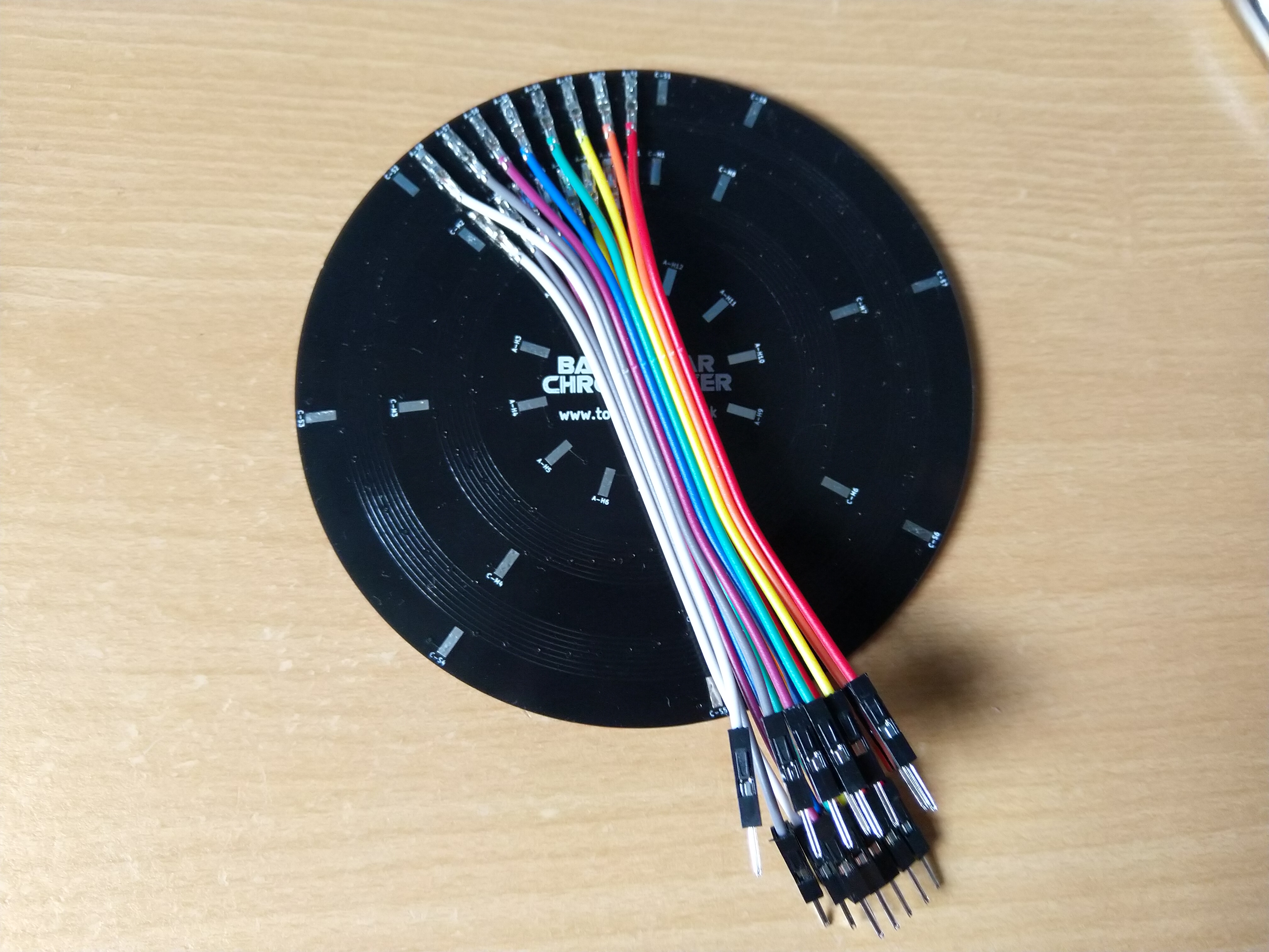
This started out well but eventually got a bit chaotic. If I do a revision 2 of this board, I may give some more thought to the positions of some of the pads.
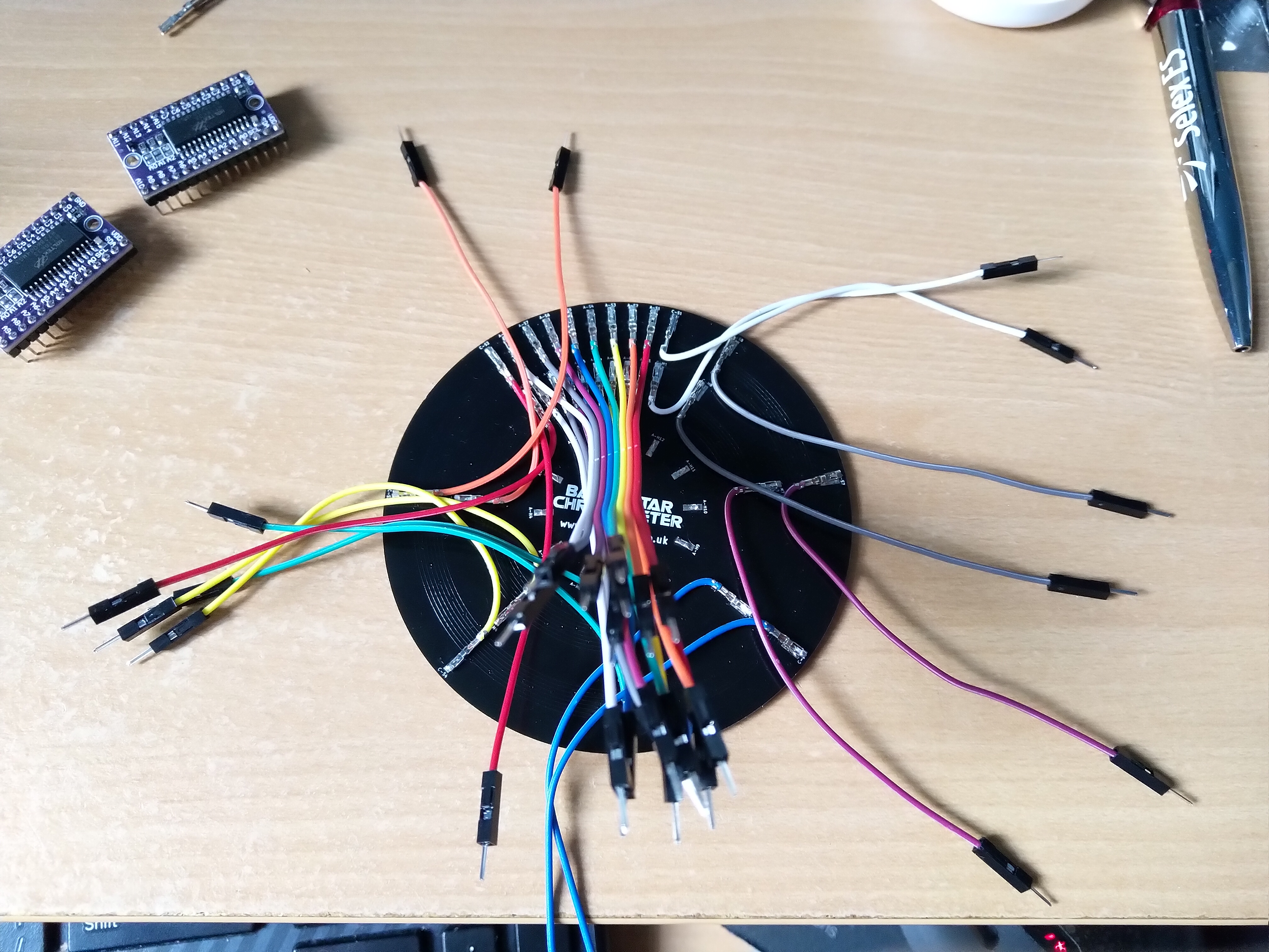
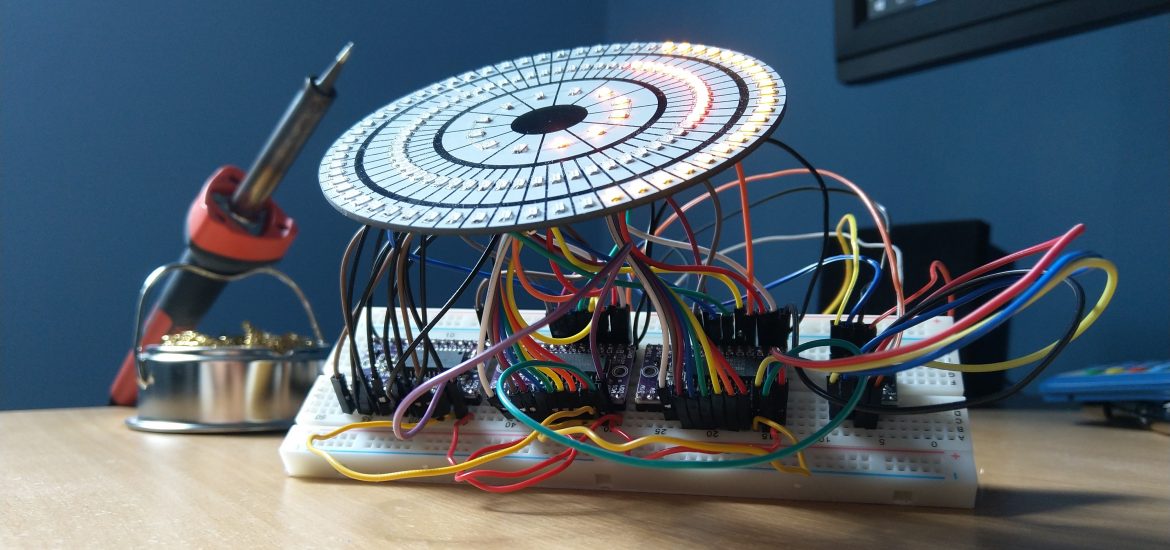
The final step was to hook the wires up to the respective driver board and give the chronometer a whirl! Connecting the wires wasn’t nearly as bad as it looks, but the code gave me a bit of a headache. The driver boards (HT16K33) and associated Adafruit driver expect the LEDs to be connected in rows of 16, whilst mine were connected in rows of 8. A little bit of fiddling later and I’d written an LED test script:
This identified only a single LED that needed resoldering because of a bad connection. While three driver boards is probably overkill, it does allow me to adjust the brightness of each ring. This is especially useful as the red LEDs are much brighter than the orange and yellow. A little bit more coding and the PCB was able to display the time:
I think the next step is to figure out how to tidy the wiring and driver boards. The current setup isn’t really stable or practical. I might hook the orange LEDs up to the same driver board as the yellow, but I’m thinking maybe I need to design some sort of motherboard?