So this is a project that has maybe been percolating for 7 years or so and now I feel confident enough to tackle it!
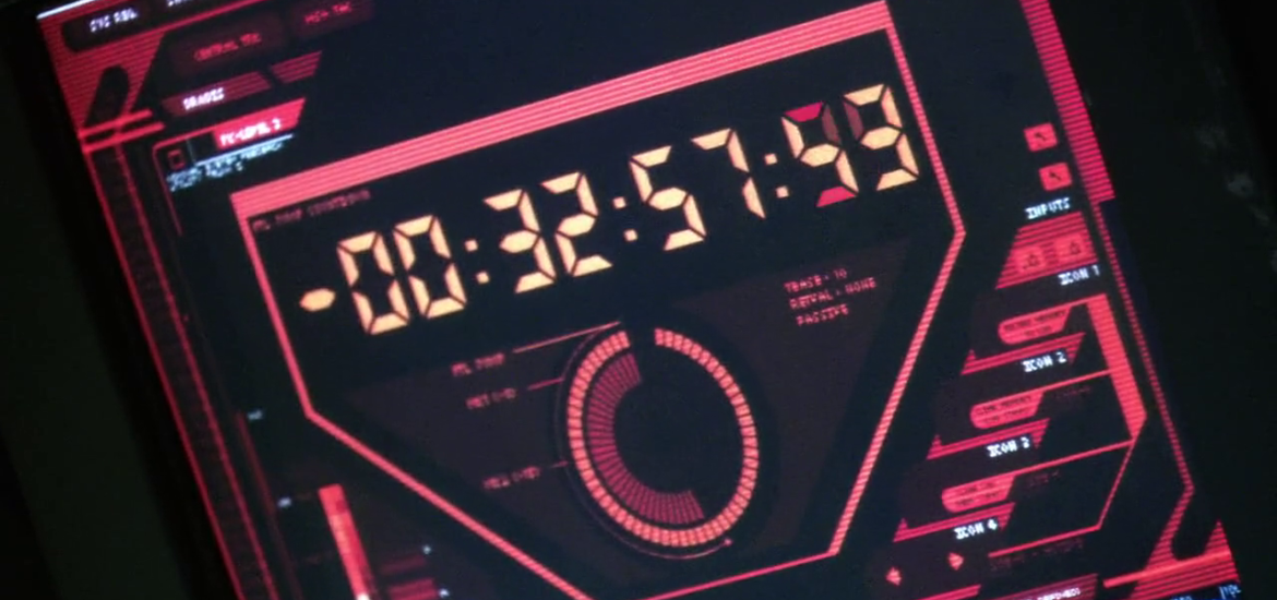
Back when I was first learning electronics, I was also playing a lot of the brilliant Battlestar Galactica boardgame. Naming no names, certain friends used to take forever on their turns, so it occurred to me that I could inject a little of the tension from the series by adding a turn timer similar to the one in the show.
I started off with an Arduino, a breadboard and a 7-segment display I had lying around and mocked up the following (sorry for the poor quality, it was 2011):
A good start, but ambitious me from 2011 really wanted to replicate the circular countdown. I started by buying a lot of 5mm LEDs, 400 to be precise! I then spent a lot of time trying to figure out how I’d not only wire all these LEDs, but also construct some sort of frame to house them. This was well before I’d encountered either PCB fabrication or 3D-printing, so this was a bit of a struggle. Long story short, I ended up building my first LED matrix as a proof of concept of the ideas, but never really progressed the idea any further.
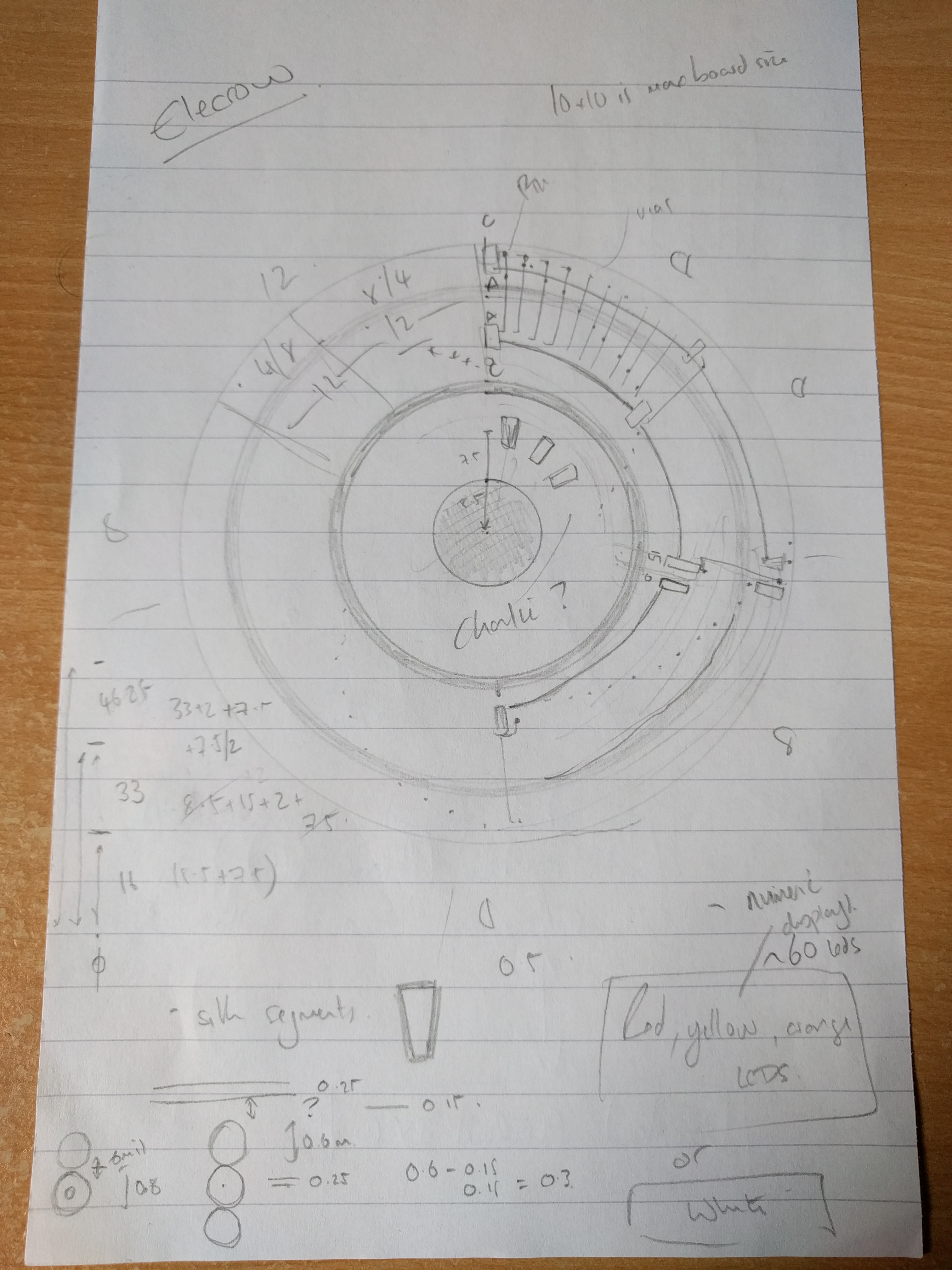
Fast forward to 2018 and I now posses the right range of skills to tackle this project again. After finishing the Clamps badge I was looking for a meatier project to get stuck into when this project popped back into my head and it seemed like a perfect fit! Here’s one of the many sketches I did to try and get my head around what I was doing:
Modular PCBs
Quite early on it occurred to me that any PCB I designed would contain repeated elements, so I spent a lot of time trying to split the board up into modular elements that could be soldered together to make a complete PCB. The idea being that I could take advantage of the fact fab houses tend to insist on a minimum quantity of 3 or 5 boards per order. In the end this was a bigger headache that it was worth and decided to live with receiving more boards than I wanted.
EAGLE vs KiCAD
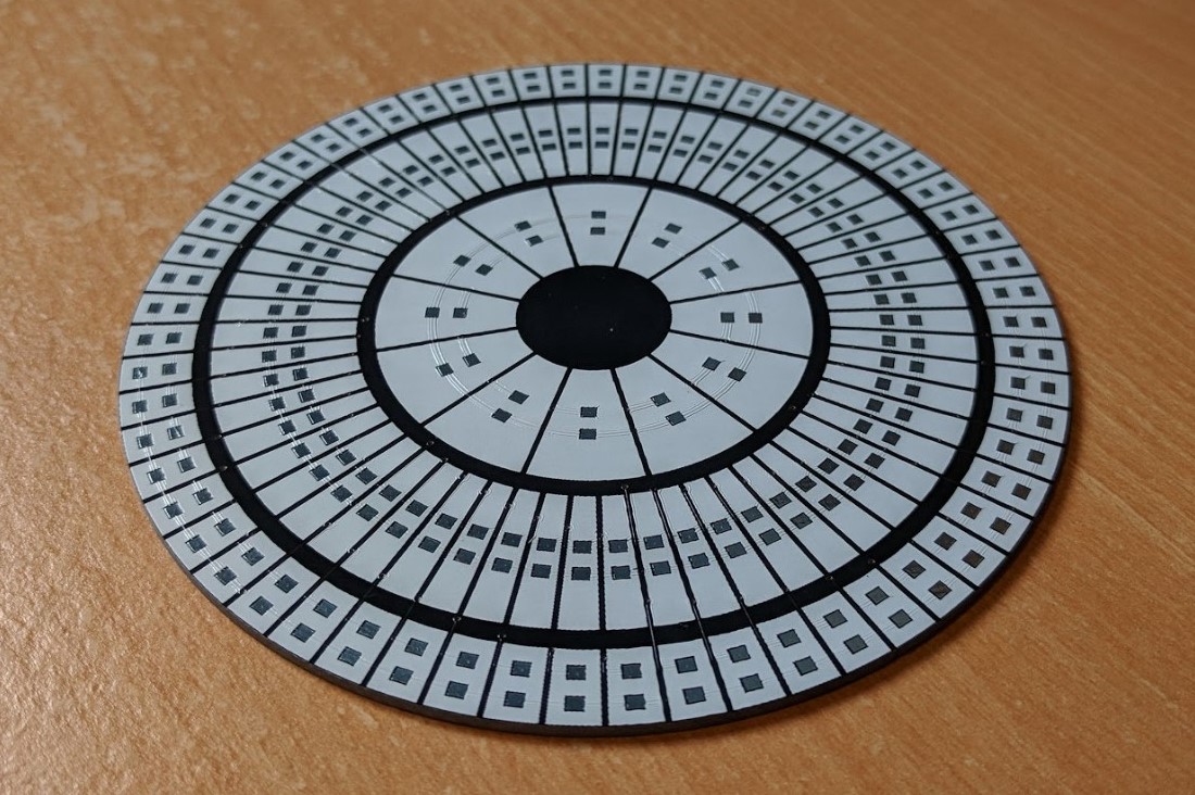
This however led to my next problem. The maximum board area supported by EAGLE is 80cm2 in the free version I have and I wanted this thing to be big! So after a bit of a Google I decided to try out KiCAD. I managed to pick it up quite quickly and stumbled across the Python scripting interface. The idea of laying out 132 LEDs by hand was terrifying so I started to poke at the layout using Python. Initially progress was quite slow but I eventually got to a point where I could open a blank PCB run a script and end up with something like the following:
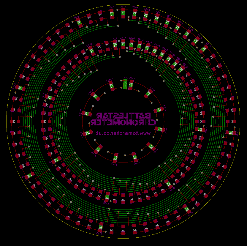
If I was unhappy with anything (which I regularly was) I could delete everything, tweak the script and re-run it to generate the new layout. I have 4 distinct project files for this board, but I must have laid this board out a hundred times over the course of the project. The code was a mess but it worked!
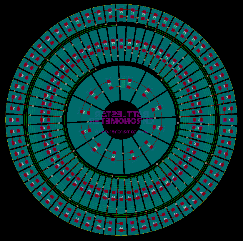
While the layout looks a bit complicated, the ‘minutes’ and ‘seconds’ rings are essentially each just an 8×8 common-cathode LED matrix spread out in a line. The ‘hours’ ring is just a line of 12 LEDs with their cathodes connected. The anode and cathode connections for each matrix are routed to the back of the board behind specific LEDs. The advantage of this is that there are a number of driver chips that support these sort of matrices and while Charlieplexing might have been better, it made my head hurt to think about how I’d route these LEDs!
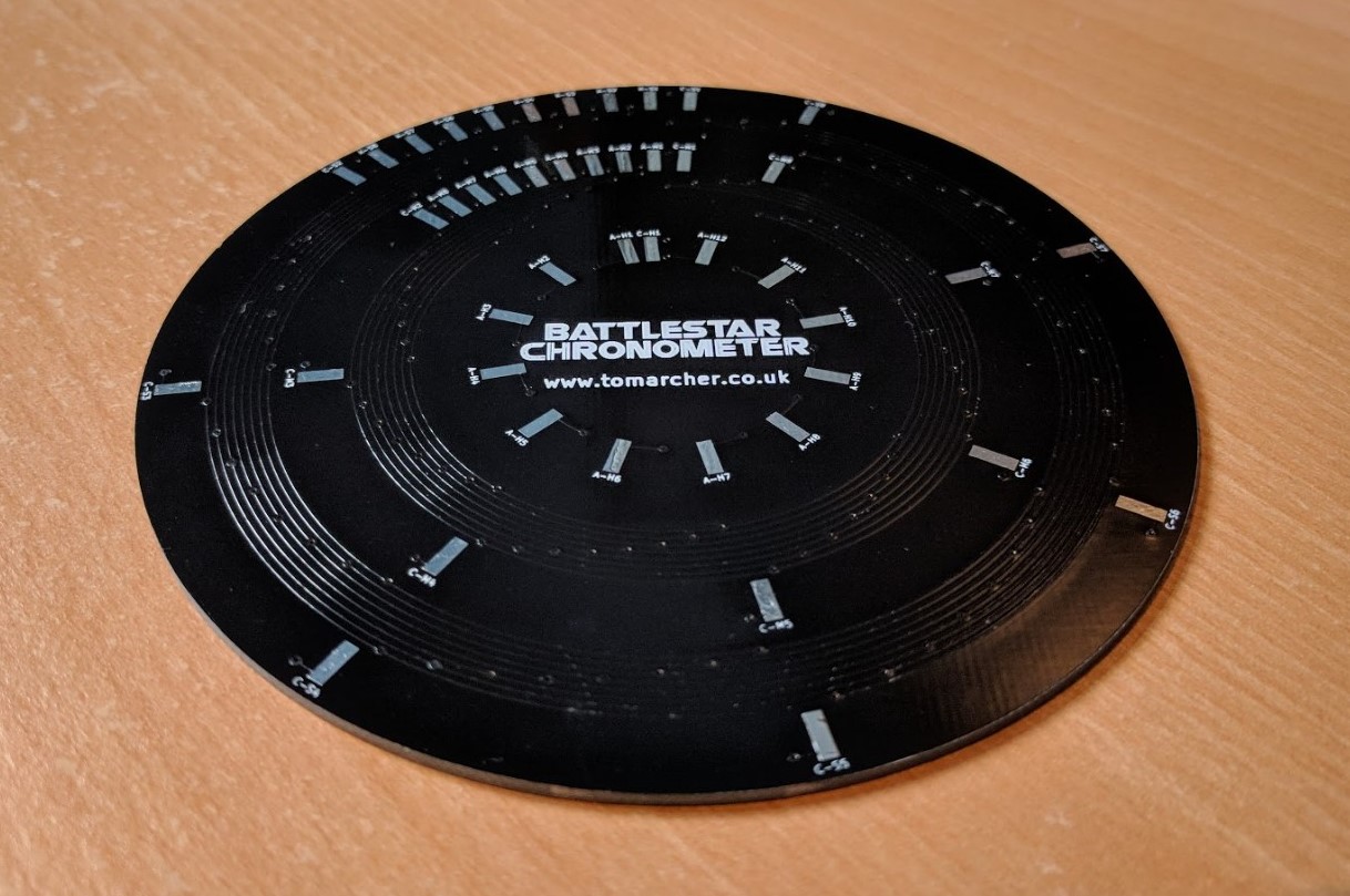
Some of the routing is a little bit weird, but I really wanted to avoid having vias intersect my silkscreen:
Compared to Eagle, importing silkscreens was a doddle. I now wish I’d designed my Clamps badge in KiCAD and will definitely be tempted to use it for future projects.
Fabrication
For fabrication, I’ve sent it off to Elecrow once again. As ever the turnaround was incredibly quick and I now have six of these boards to play with: