Like many I’ve been working from home over the last year or so. While I have a reasonable speaker system connected to my desktop PC, I can’t use it while I’m working on my laptop. The solution as ever lies in a custom PCB!
Before I ended up designing a PCB, I did have a look in a few places (Amazon, Tindie) for off the shelf products which would do what I wanted. Unfortunately most of the cheaper solutions I came across were only mono-audio and the more expensive options had features that I didn’t need, like volume control or a mute button.
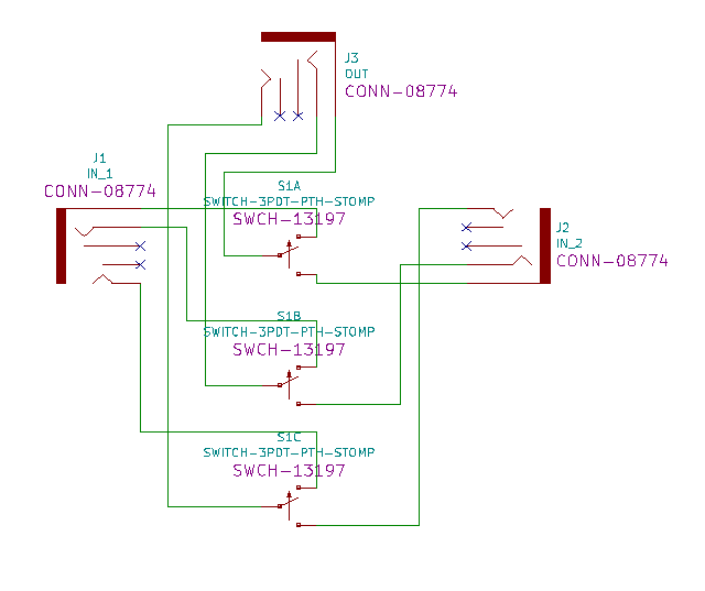
The schematic was fairly straight forwards, three 3.5mm audio jacks connected via a 3PDT switch. The 3PDT is a defining feature of this design as other stereo-audio switchers tend to tie the ground connections of all three jacks together. This is a common source of “hum” and something I really wanted to avoid.
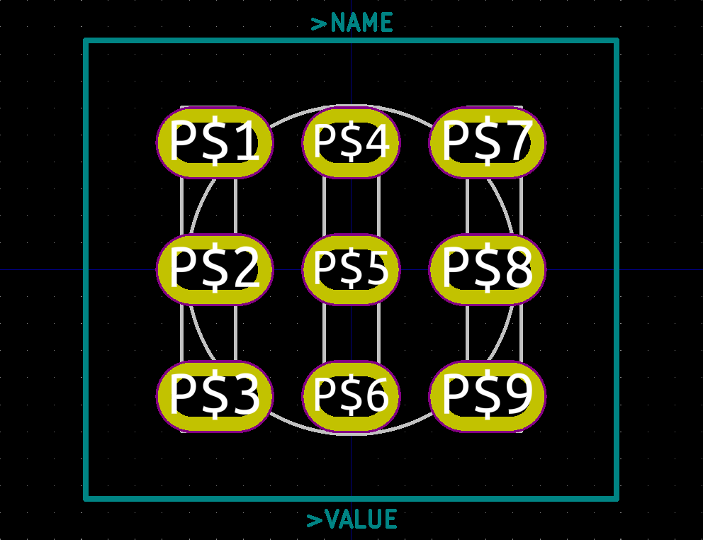
The switches I had in mind aren’t normally PCB mounted, rather they’re meant to mounted in a panel/enclosure and attached to the PCB with flying wires. This is another source of possible interference so I designed my own switch footprint to allow it to be PCB mounted. As I wasn’t entirely sure what type of switch I was going to use in the final assembly, I designed in some “wiggle-room” which should also help if the switches aren’t precisely manufactured.
Onto the PCB layout, I decided to use the same form-factor as the PCB I designed for the RCA Audio Attenuator, more on that later.
I had to be a bit careful about how I positioned the “input” audio jacks in relation to the switch as, in the event I used a toggle switch, I wanted it to point in the direction of the selected input, rather than away from it. This took some back and forth between the schematic and the PCB layout as I tried to find the optimal way to route the tracks. Again to avoid any potential sources of interference I laid the board out without vias or crossing of tracks.
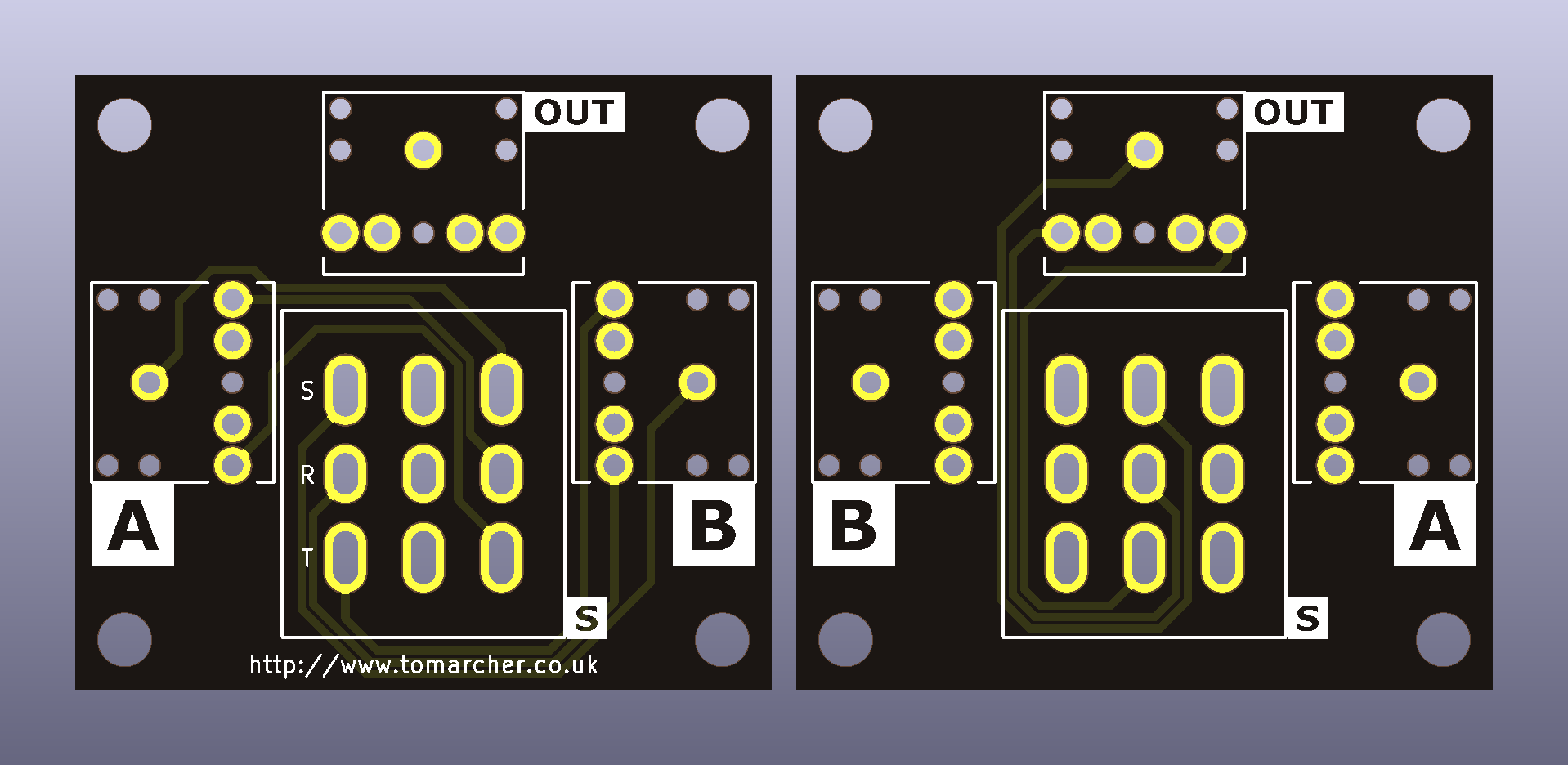
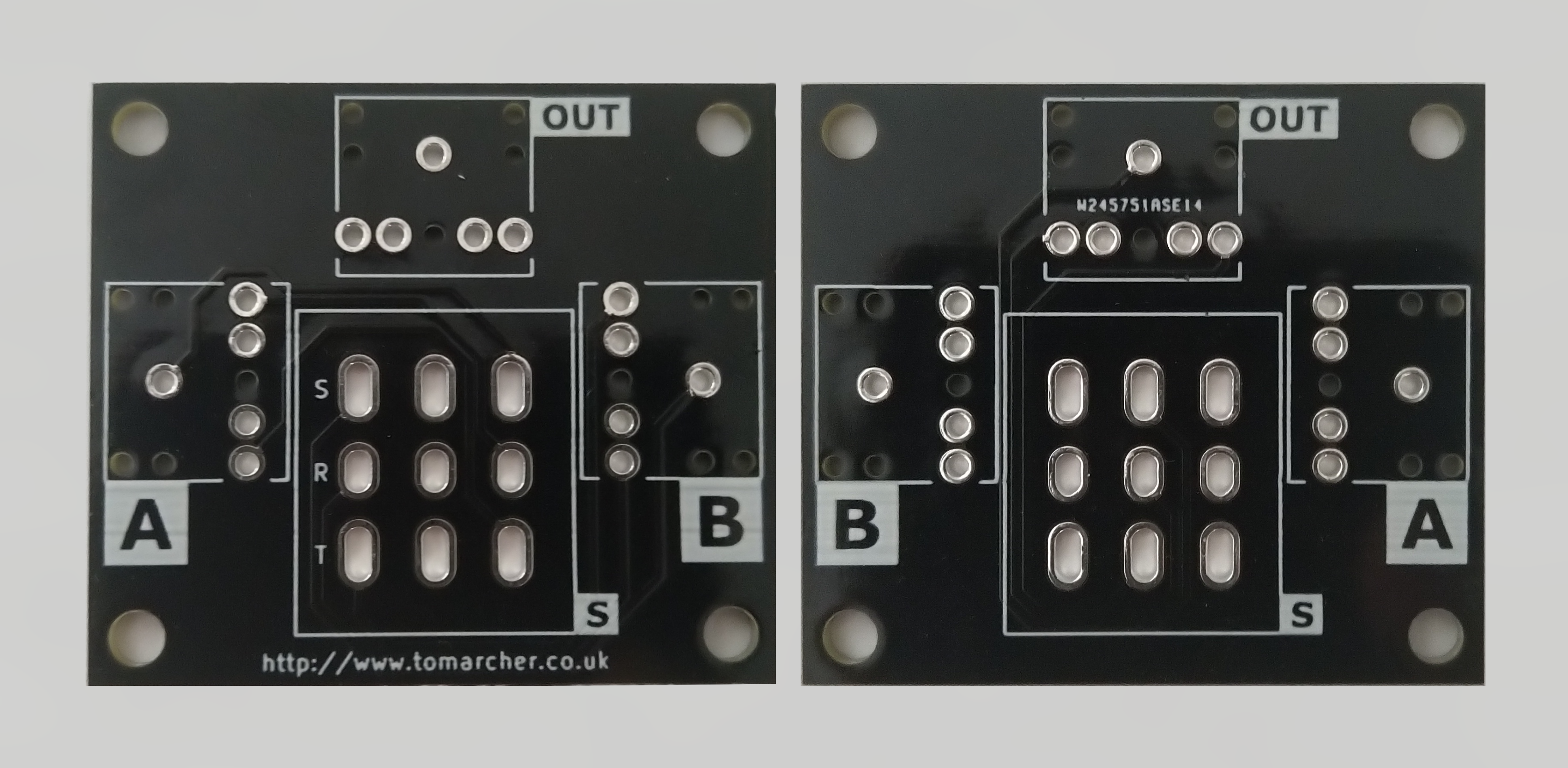
The components were labelled in my usual style using svg2shenzhen. Since this board will be able to switch two inputs to a single output or one input to two outputs, I took a bit of time to get the jack labels right. In the end I drew inspiration from cassette/vinyl “A” and “B” sides. Hopefully they make sense regardless of which “direction” it’s being used in.
As ever the boards were manufactured by PCBWay and again, no complaints.
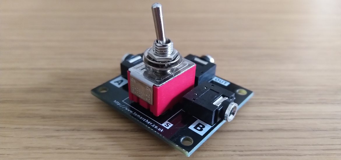
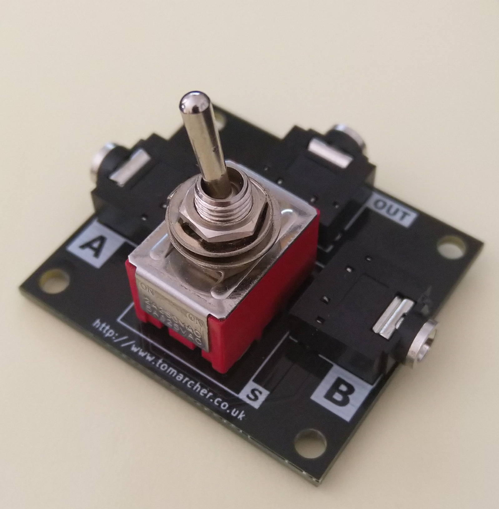
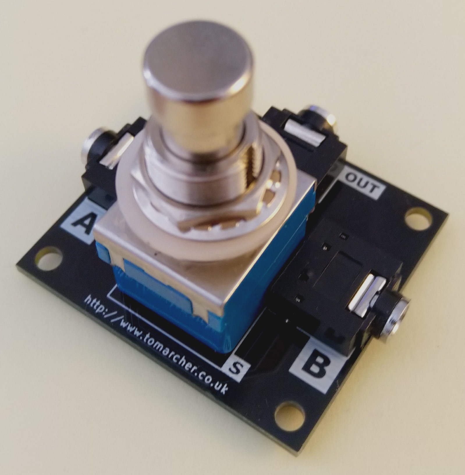
Next up was the assembly. I ordered a couple of different 3PDT switches. On the left you have a standard toggle switch and on the right you have a “stomp” switch intended for guitar foot pedals.
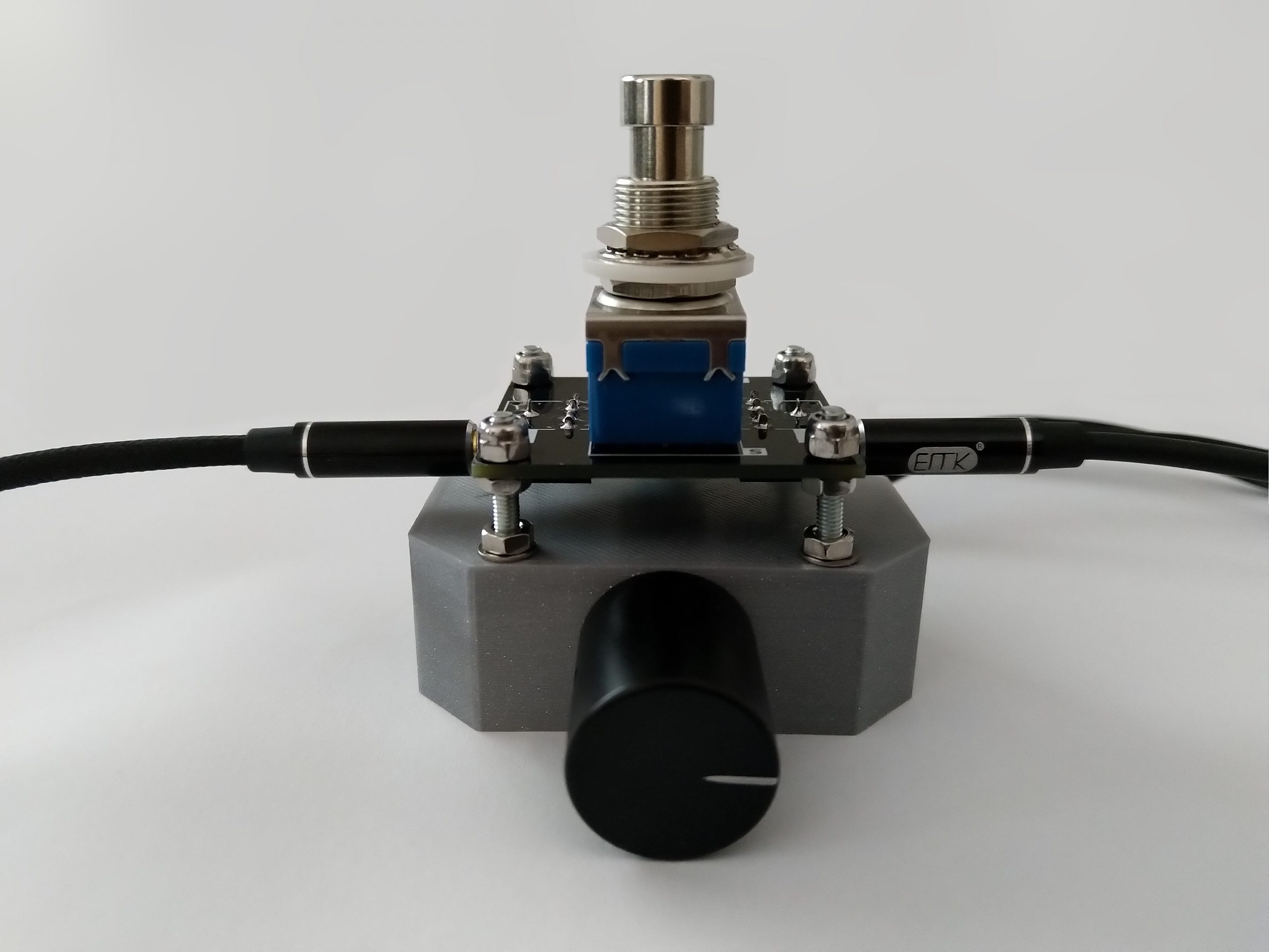
For my use I prefer the “stomp” switch so I set about hooking it into my current audio setup. As I mentioned earlier, this PCB has the same form factor as my Audio Attenuator board. This was for good reason, I’d planned to attach it to my second Audio Attenuator and mount both under my new desk. This was a fairly simple modification, I drilled out the old 3D printed PCB posts and added some bolts, nuts and washers. Here’s a photo of the final assembly, albeit upside-down:
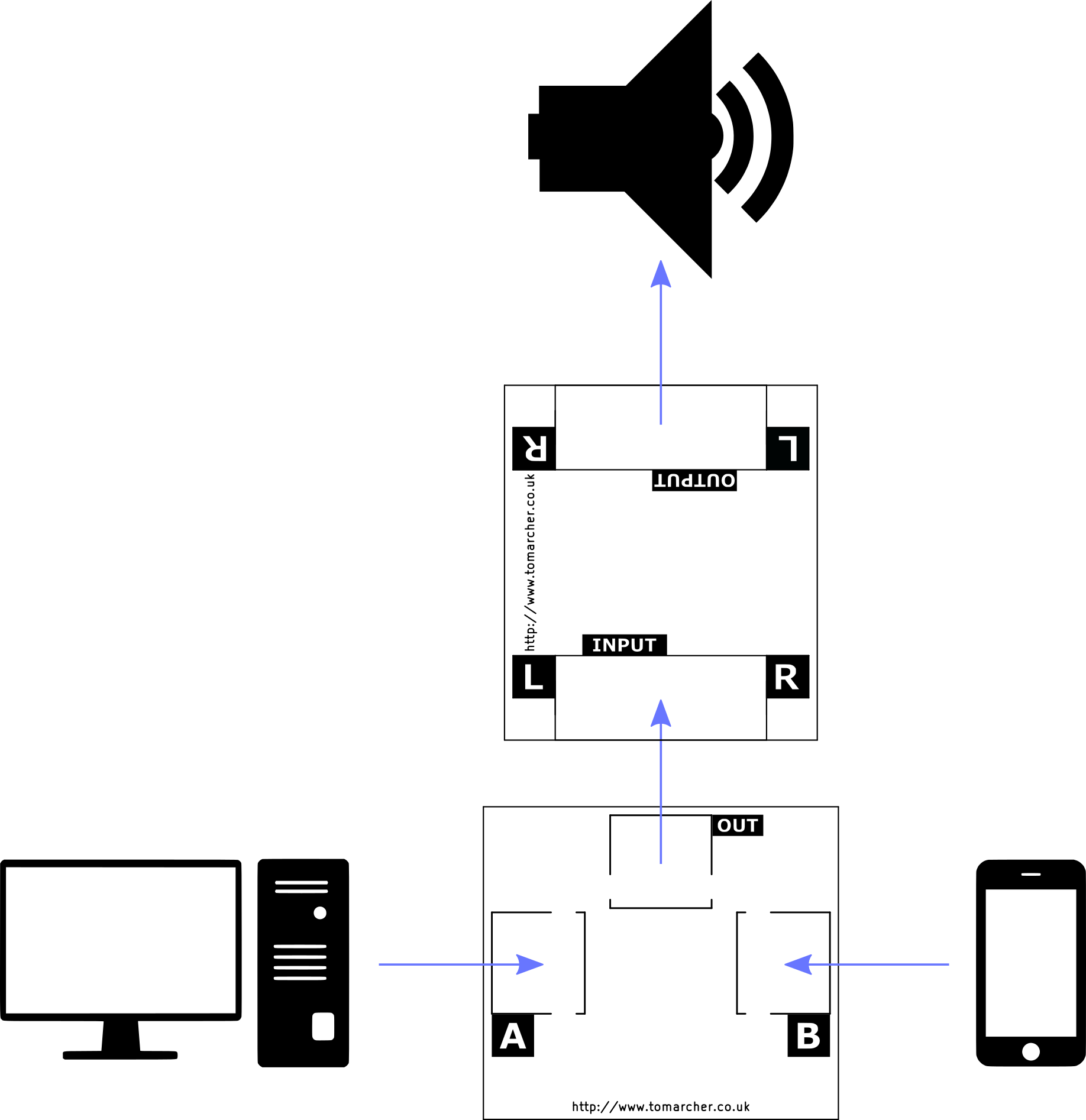
I’ve got one of the Switcher inputs permanently connected to my PC and the other is temporarily connected to my phone as I need. The Switcher output is connected to my PC speakers via the Audio Attenuator. This means I have fine control over the volume of whichever input is selected. Here’s that as a diagram:
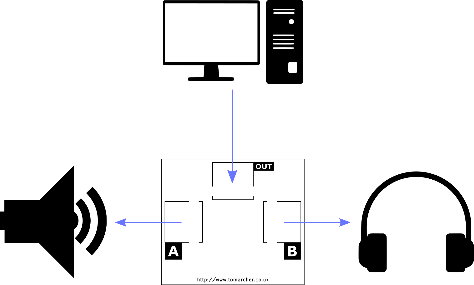
This is just one of two supported use cases. Alternatively you might connect one audio source, (e.g. a PC) to two different outputs, (e.g. speakers and headphones) and swap between the two at the flip of a switch.
As I was originally unable to find any products that met my needs, I began this project with the intention of eventually selling some kits on Tindie. If this is something you’d find useful, there are a small number available here.