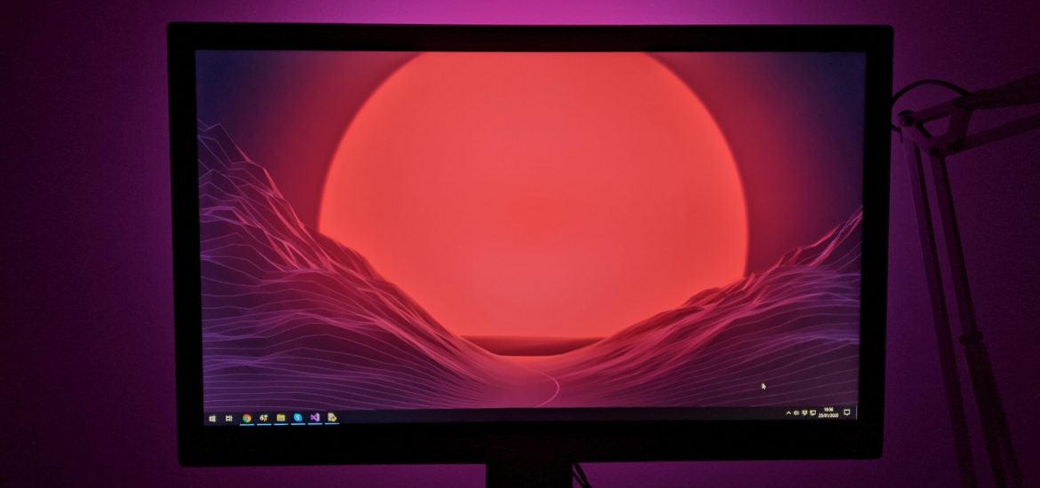
When I moved house I disassembled my bookshelf lighting and my Mote kit has been sitting in a box since. I’ve been looking for something to do with them and it struck me that the Mote sticks are the perfect size to be mounted behind a monitor for a DIY Ambilight setup.
Ambilight setups such as those found on Philips televisions capture the the onscreen colours and project them onto the wall behind using a set of LEDs thus extending the screen area. I tend to use my PC monitor for films and games and while aftermarket versions such as Lightpack are also available they are a little expensive. The Mote kit seems like a perfect candidate for a DIY setup, being powered and controlled by a PC USB port.
A quick Google found me the Adalight system which uses a Processing script to capture the screen colours and output them to an Arduino connected to a WS2801 LED strip. I briefly considered converting the Processing script to a Python script so that it’d work with my Mote device, but before I did I stumbled across this series of blog posts which create an Ambilight using WS2812B LEDs.
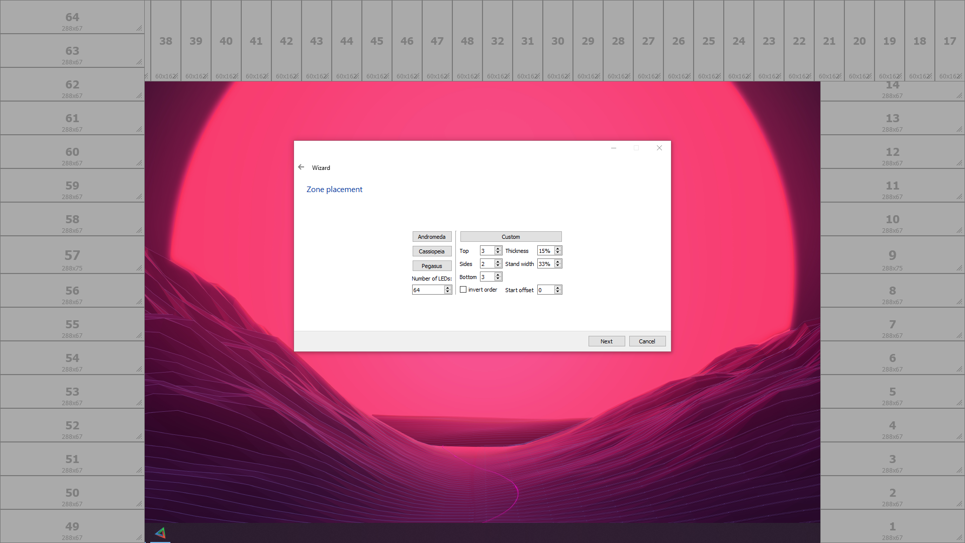
Crucially while still being based on the Adalight/Arduino setup, this DIY Ambilight does away with the Processing script and replaces it with the Prismatik application. This software is pretty feature-rich and on top of doing the complicated grabbing of screen colours, it has a drag and drop interface for positioning the screen regions as well as some options for colour calibration.
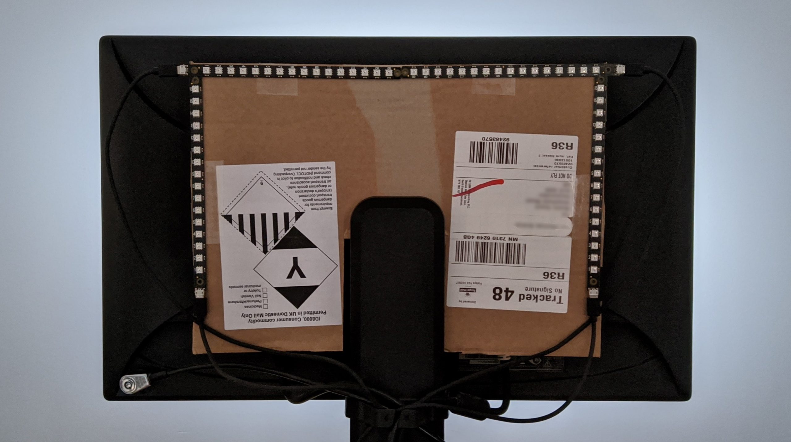
This is my setup for a single mote stick on each side of the screen and two mote sticks running across the top. My mechanism for attaching these to the screen is a little crude, consisting of cardboard and double-sided tape, but it works for now:
Prismatik is originally intended to be used with Lightpack devices but also supports Adalight and Ardulight devices using serial communication over USB. I could possibly have used a Raspberry Pi in place of the Arduino and then piped the commands across to the Mote, but I really didn’t want an extra device in this setup. Fortunately the software is open source, so I set about modifying it.
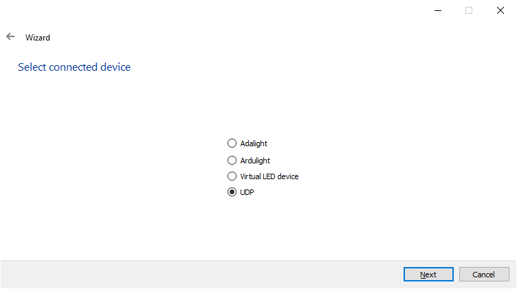
I essentially took a copy of the code for the “Virtual LED device” and modified it to also output the colours to a UDP socket using the same message format as Adalight. I’ve done this on a fork of the repository but at some point I hope to raise a pull request and get it merged back in to the main branch.
A very basic Python script listens for these packets and uses the colour information to set the Mote sticks appropriately:
from socket import *
import atexit
from mote import Mote
leds = 64
pixels = 16
gamma_correction = False
mote = Mote()
mote.configure_channel(1, pixels, gamma_correction)
mote.configure_channel(2, pixels, gamma_correction)
mote.configure_channel(3, pixels, gamma_correction)
mote.configure_channel(4, pixels, gamma_correction)
mote.clear()
mote.set_pixel(1, 0, 255, 0, 0)
mote.show()
recvSocket = socket(AF_INET, SOCK_DGRAM)
recvSocket.bind(('', 7755))
while True:
message, address = recvSocket.recvfrom(1024)
if (len(message) == 198):
mote.clear()
for led in range(leds):
mote.set_pixel(led//16+1, led%16, message[6+(led*3)], message[6+(led*3)+1], message[6+(led*3)+2])
mote.show()
@atexit.register
def close():
recvSocket.close()
Code language: Python (python)This currently has to be run manually, but I’m going to look at setting this script to run at startup.
I’ve borrowed the colour test and game test put together by the Parts Not Included blog and they look pretty spectacular:
I think there’s still a little bit of tweaking that can be done with regards to colour calibration and LED positioning, but I’m really pleased with how this project has turned out.