For the last few years I’ve taken part in the local Rampaging Chariots competition along with a group of graduates. One of our most recent challenges has been to get a rover to autonomously navigate the assigned assault course. So lately I’ve been thinking a lot about odometry, that is, estimating the position of a robot over time. Typically, a cheap method of tracking the position of a rover is by attaching rotary encoders to the output shaft of the drive wheels. Unfortunately as the traction of the drive wheels isn’t perfect, they will slip occasionally and introduce errors into the estimated position.
Computer mice perform a very similar task. By taking low resolution photos a surface they’re able to very accurately track their relative position. If you were able to mount one (or more) of these under a rover, it might prove to be a better odometry solution.
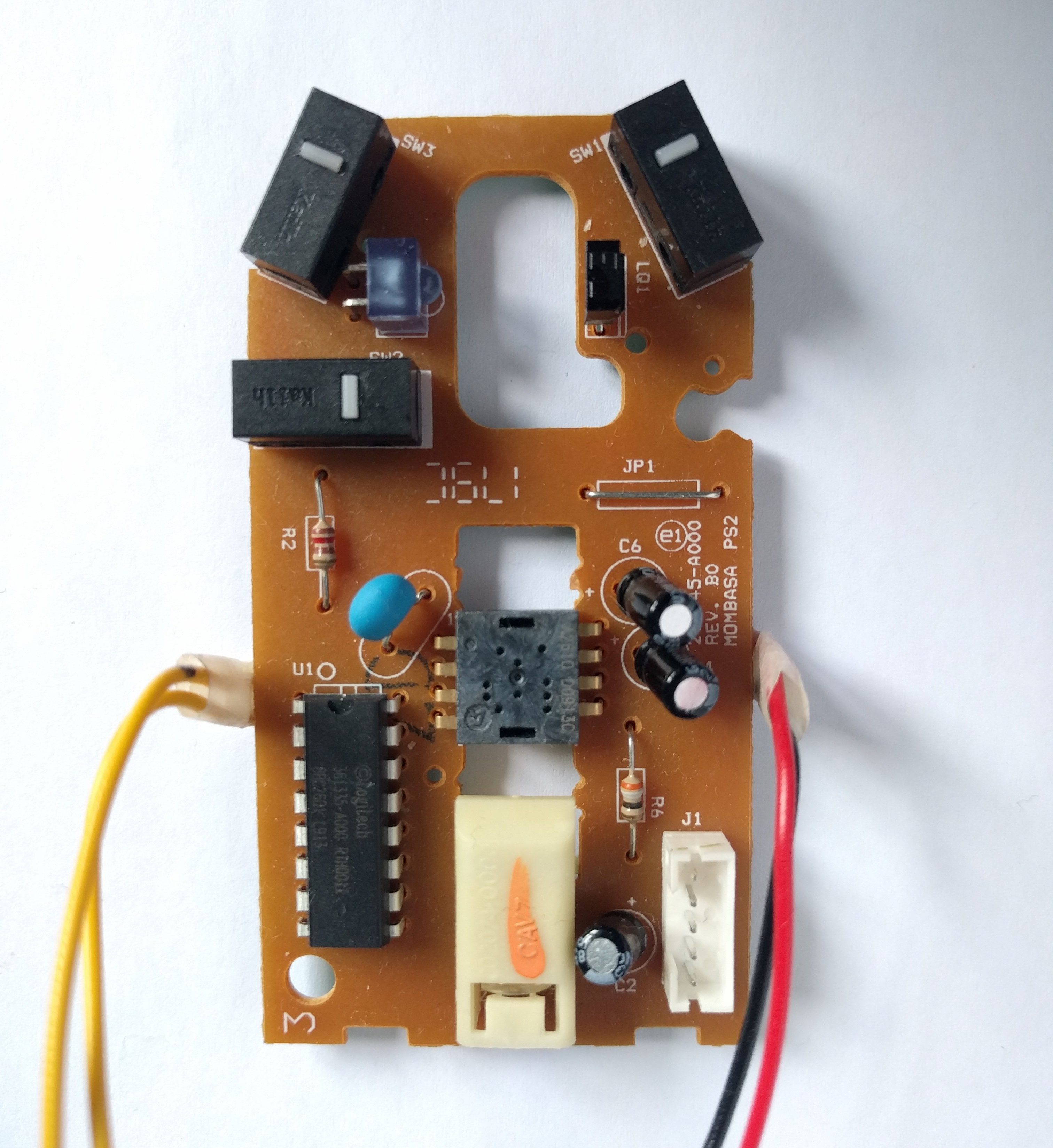
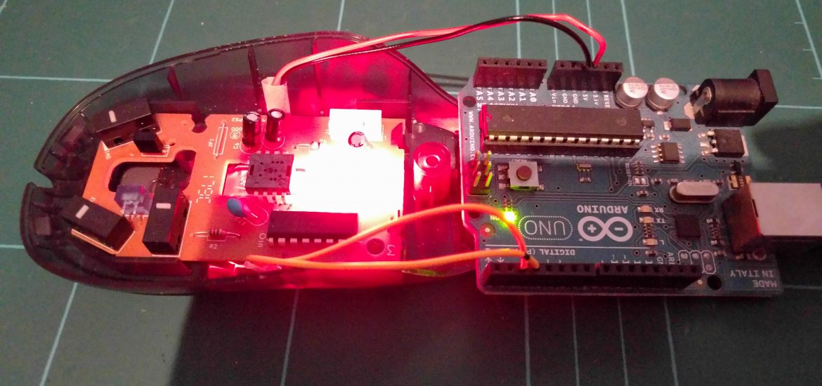
The photo above is the main board from an old HP mouse that I dug out. You’ll notice the tactile switches up at the top, a micro-controller in the bottom left and the important optical sensor is sitting right in the centre. After a bit of research I managed to dig up a data sheet. The chip implements a simple serial protocol, so I hooked up some wires to the 5V, ground, clock and data pins. Fortunately I found someone who had already written an Arduino driver for a similar chip so all I had to do was change a few register addresses and I was ready to experiment.
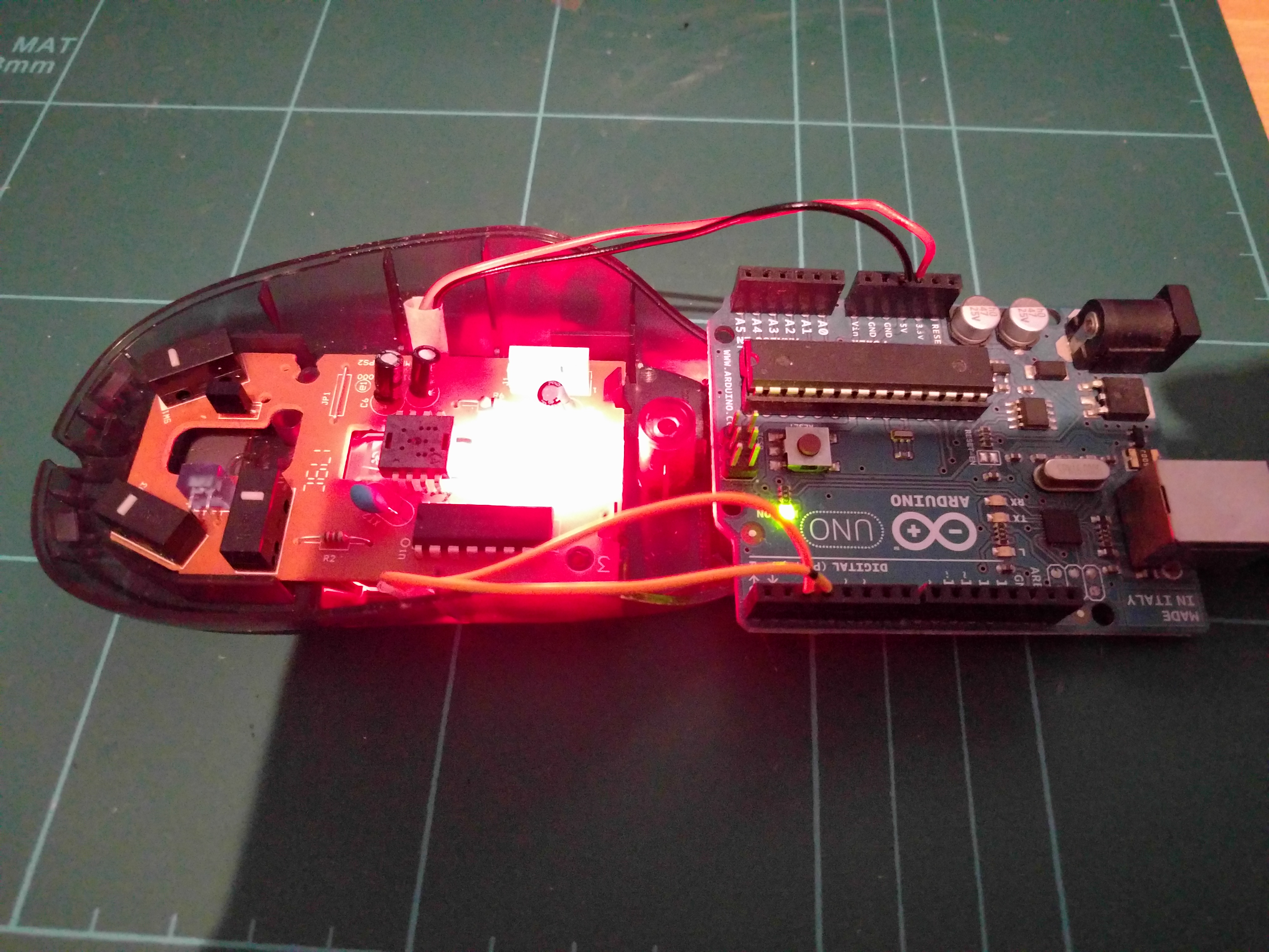
I added a little bit of code in order to covert the register data to centimetres and send it to the PC via the Arduino’s serial port. On the whole the data I got back seemed incredibly accurate so I decided to press on! With all the excess electronics, the next step was to separate the core components. At this point I came across a dead Microsoft Intellimouse which had a more compact lens assembly.
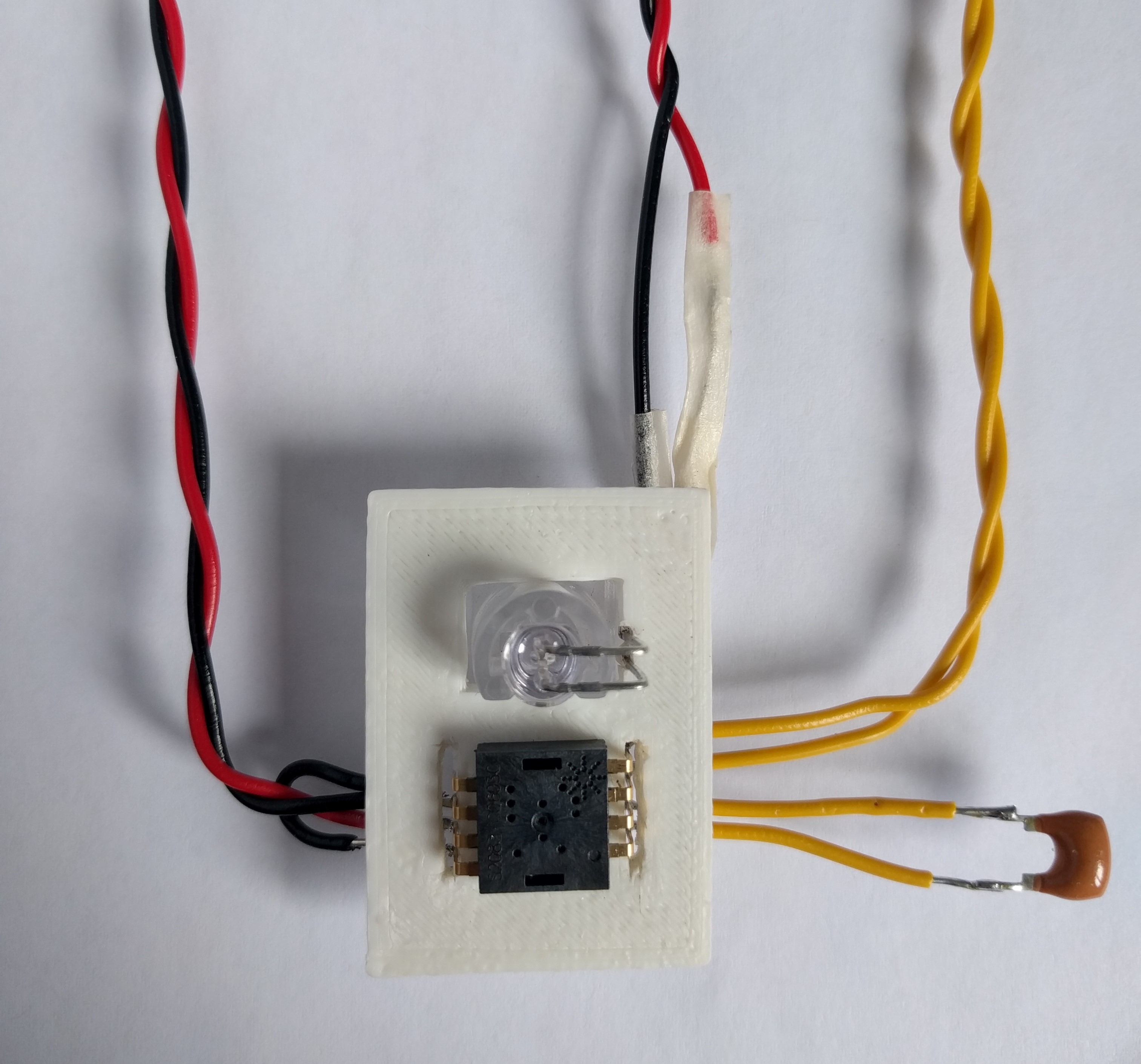
Returning to the datasheet, I was able to figure out that aside from the sensor, I also needed to extract the crystal oscillator, LED & resistor and a smoothing capacitor. The resistor itself was surface mount so I picked up the nearest through hole equivalent. It’s only used as a current limiter for the LED, so not all that important that it was exact. In fact the LED is very bright so I probably could have gone a little higher.
The original plan was to move all these parts over to some veroboard, but unfortunately the optical sensor has an annoying staggered pin layout. To keep all the loose components together while I continued to test the sensor, I printed a little mock ‘circuit-board’.
The project took a little pause here while I set about learning how to design a custom PCB. We’ll pick that up in part two.
As ever the code for this project is available on my GitHub.